






Railway Grounding Resistance Tester for Railway Safety
September 30, 2026
What Is a Railway Grounding Resistance Tester?
A railway grounding resistance tester is a field instrument used to measure the resistance of a grounding or earthing system.
It may be used in:
- Railway stations
- Traction substations
- Trackside signaling systems
- Communication equipment
- Overhead line structures
- Lightning protection systems
- Railway control cabinets
- Grounding grids and electrodes
The purpose of the test is not simply to obtain the lowest possible resistance value. The grounding system must also provide a safe path for fault current, help control touch and step voltages, and work correctly with the traction return circuit and signaling system.
Because railway grounding arrangements differ between projects, the acceptance criteria should come from the applicable railway standard, project specification, or local authority requirement.
Why Grounding Testing Is Important
Protecting People from Induced Voltage
Railway tracks and nearby metal structures can develop induced voltages because of traction current, overhead lines, switching operations, and electromagnetic coupling.
A properly designed grounding and bonding system helps control these voltages and reduces the risk of electric shock for railway workers and maintenance personnel.
Protecting Signaling and Communication Equipment
Railway signaling and communication devices are sensitive to surges and electrical interference. Lightning strikes and traction faults can introduce high currents through power cables, communication cables, or metal structures.
A reliable grounding system helps divert surge energy and provides a more stable reference potential for sensitive electronic equipment.
Supporting Traction Power Safety
Grounding is closely connected with the traction power and return-current systems. A properly designed arrangement helps provide a predictable path for fault current while limiting dangerous potential differences.
However, the rail return circuit and protective earth are not necessarily the same thing. Their connection depends on the railway design. An incorrect connection can cause stray currents, corrosion, or interference with train detection systems.
Maintaining Signaling Reliability
In some railway systems, the rails form part of the track circuit used for train detection. For this reason, any grounding or bonding work must be planned carefully. A grounding connection that improves electrical safety in one area could interfere with signaling if it is installed incorrectly.
Factors That Affect Grounding Resistance
Grounding resistance is influenced by the design of the system as well as local environmental conditions.
Soil Resistivity
Soil moisture, mineral content, temperature, and salt concentration all affect conductivity. Dry, frozen, or rocky soil usually produces higher resistance than moist soil with better conductivity.
Seasonal changes can therefore cause noticeable differences between measurements taken at different times of the year.
Electrode Depth and Arrangement
The depth, length, number, and spacing of grounding electrodes all affect the final result. A deeper electrode may reach a soil layer with better conductivity, while additional electrodes can increase the effective contact area.
However, simply adding electrodes does not always solve the problem. Their spacing, mutual influence, and connection to the grounding grid must also be considered.
Corrosion and Loose Connections
Grounding conductors and electrodes are exposed to moisture, chemicals, stray current, and changing soil conditions. Over time, corrosion can reduce their cross-sectional area and contact surface.
Loose clamps, damaged bonding straps, and corroded joints can also increase resistance or create an intermittent connection.
Weather and Climate
Drought, heavy rainfall, flooding, and freezing conditions can all change soil conductivity. Test records should therefore include the weather, soil condition, temperature, and date of measurement.
How to Test a Railway Grounding System
The actual procedure depends on the grounding design and the measurement method. Common methods include the fall-of-potential method, soil resistivity testing, selective testing, and clamp-based testing where the system configuration allows it.
A typical field inspection includes the following steps.
1. Review the Grounding Arrangement
Before connecting the tester, identify the grounding electrode, grounding grid, bonding conductors, rail connections, and nearby metal structures.
Check whether the system is connected to:
- Traction substations
- Signal equipment
- Communication systems
- Cable screens
- Lightning protection systems
- Other grounding grids
Unexpected parallel paths can affect the result and may create safety issues during testing.
2. Confirm Whether Isolation Is Required
Some railway grounding systems remain connected to rails, return circuits, or operating equipment. Any disconnection must follow an approved railway maintenance procedure.
Before isolating a conductor, confirm the traction power status, work authorization, induced-voltage risk, and impact on signaling and communication systems.
3. Connect the Tester
Connect the current and potential leads according to the selected test method. Auxiliary electrodes must be installed at suitable distances and should make reliable contact with the soil.
Poor electrode contact, buried metal objects, unsuitable spacing, and parallel grounding paths may all produce inaccurate readings.
4. Check for Electrical Interference
Railway environments are often affected by traction current, substations, overhead lines, and signaling equipment. Strong interference may cause unstable or fluctuating results.
If the tester includes interference detection or selectable test frequencies, use these functions according to the manufacturer’s instructions.
5. Repeat and Record the Result
Repeat the measurement after checking the wiring and electrode contact. If the values vary significantly, investigate possible causes such as:
- Loose test leads
- Poor auxiliary-electrode contact
- Nearby energized conductors
- Parallel grounding paths
- Soil differences
- Damaged grounding connections
- Incorrect test configuration
The result should be compared with the required limit and previous test records rather than judged in isolation.
Choosing the Right Tester
A suitable railway grounding resistance tester should be selected according to the test environment and the grounding system being inspected.
Important features include:
- Measurement range
- Accuracy and resolution
- Resistance to electromagnetic interference
- Test current and frequency
- Selective measurement capability
- Clamp testing functions
- Data storage
- Battery life
- Portability
- Calibration support
- Local technical service
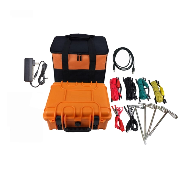
Weshine Electric Manufacturing Co., Ltd. provides grounding resistance testing instruments for power and railway electrical maintenance applications. Depending on the model, the equipment may support high-precision measurement, field testing, interference-resistant operation, and convenient data recording.
The final instrument choice should be based on the railway design, required test method, project specification, and applicable standards.
Improving Railway Grounding Performance
Measurement is only the first step. If the result does not meet the required limit, engineers may need to review the complete grounding arrangement.
Possible improvement measures include:
- Using deeper or additional electrodes
- Expanding the grounding grid
- Improving bonding connections
- Replacing corroded conductors
- Selecting materials suitable for local soil conditions
- Increasing electrode spacing where necessary
- Improving corrosion protection
Any modification should be checked for compatibility with the traction return circuit, signaling system, electromagnetic compatibility requirements, and railway safety procedures.
Frequently Asked Questions
What does a railway grounding resistance tester measure?
It measures the resistance of grounding electrodes, grounding grids, bonding systems, and related earthing components.
What is an acceptable railway grounding resistance value?
There is no single value for every railway system. The required limit depends on the traction system, grounding design, soil conditions, signaling requirements, and applicable standards.
Why does grounding resistance change with the weather?
Soil moisture and temperature affect soil resistivity. Dry, frozen, or highly variable soil can cause the measured resistance to increase.
Can a standard earth tester be used on railway infrastructure?
It may be suitable for some isolated grounding systems. However, railway sites often have parallel grounding paths and strong electrical interference, so a tester designed for power-system or railway applications may provide more reliable results.
How can grounding resistance be reduced?
Possible solutions include improving electrode depth, adding grounding conductors, expanding the grounding grid, repairing connections, and replacing corroded components.
Conclusion
Railway grounding resistance testing is an important part of railway electrical maintenance. It helps identify problems that may affect fault-current control, personnel safety, signaling reliability, and traction power operation.
Accurate results depend on the correct tester, suitable test connections, proper handling of parallel grounding paths, and careful consideration of electromagnetic interference. Regular testing, combined with maintenance records and trend analysis, allows railway operators to identify deterioration early and maintain a safer, more reliable electrical system.

