






Railway Grounding Resistance Tester: Applications, Testing Principles, and Maintenance
September 30, 2026
What Is a Railway Grounding Resistance Tester?
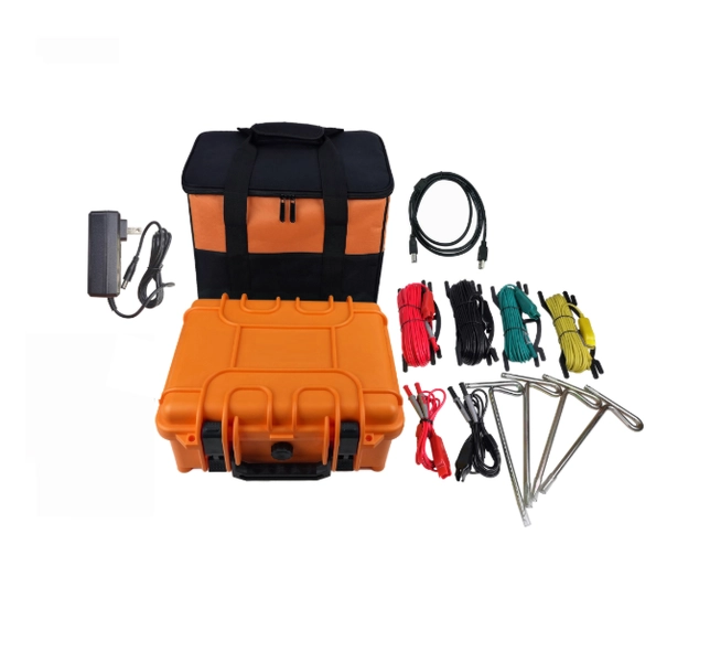
A railway grounding resistance tester is a specialized instrument used to measure the resistance of an earthing system or grounding electrode.
Depending on the application, the instrument may be used to test:
- Railway station grounding systems
- Traction substations
- Trackside signaling equipment
- Communication equipment
- Overhead line structures
- Cable shields and bonding connections
- Lightning protection systems
- Grounding grids and electrodes
- Railway control and monitoring cabinets
The test objective is not simply to obtain a low resistance value. Engineers must determine whether the complete grounding and bonding arrangement can safely control fault current, touch voltage, step voltage, lightning current, and traction return current under actual operating conditions.
Railway earthing requirements vary according to the traction system, infrastructure design, national regulations, and applicable railway standards. IEC 62128 and EN 50122 address electrical safety, earthing, bonding, and return circuits for railway fixed installations. The correct acceptance criteria must therefore be taken from the project specification and the relevant local standard.
Why Railway Grounding Testing Is Important
1. Reducing Dangerous Induced Voltage
Railway tracks and nearby metallic structures may experience induced voltages caused by traction systems, parallel conductors, switching operations, and electromagnetic coupling.
A correctly designed and maintained earthing and bonding system provides controlled current paths and helps limit hazardous potential differences. This reduces the risk of electric shock and protects personnel working near tracks, substations, and overhead line equipment.
2. Protecting Signaling and Communication Equipment
Railway signaling and communication systems are sensitive to electrical interference and transient overvoltage.
Lightning strikes, switching surges, and traction faults can introduce high currents into equipment through power cables, communication cables, or metallic structures. A reliable grounding system helps divert surge energy and maintain a stable reference potential for sensitive electronics.
3. Supporting Traction Power Safety
Grounding and bonding are closely related to the traction return circuit. A properly engineered system helps provide predictable paths for fault and return currents while controlling touch voltage and stray-current risks.
However, the rails, return circuit, and protective earth should not automatically be treated as identical. Their relationship depends on the railway design and applicable safety requirements. Improper connections may create unwanted circulating currents, corrosion, or interference with signaling systems.
4. Supporting Signal Transmission
In some track circuit systems, the rails form part of the signal circuit. Grounding and bonding arrangements must therefore be designed carefully so that protective measures do not interfere with train detection or signaling performance.
Testing should be performed according to the railway signaling design, isolation requirements, and approved maintenance procedure.
Main Factors Affecting Railway Grounding Resistance
Grounding resistance is influenced by both the physical grounding system and the surrounding environment.
Soil Resistivity
Soil moisture, mineral composition, temperature, and salt content all affect soil resistivity. Dry or rocky soil generally provides poorer conductivity than moist soil with a suitable mineral composition.
Measurements may change seasonally, especially in areas affected by drought, freezing, flooding, or significant rainfall.
Grounding Electrode Depth and Configuration
The depth, length, number, spacing, and arrangement of grounding electrodes affect the current-dissipation area.
In many situations, a deeper or larger grounding arrangement can reduce resistance. However, simply adding electrodes is not always the best solution. Electrode spacing, mutual interference, soil layers, and the overall grounding-grid design must also be considered.
Corrosion and Aging
Grounding conductors and electrodes may corrode after long-term exposure to moisture, chemicals, stray current, or changing soil conditions.
Corrosion can reduce the effective cross-sectional area and contact surface of the electrode. Loose joints, damaged bonds, and deteriorated connectors can also increase resistance or create intermittent connections.
Climate and Seasonal Conditions
Temperature and weather conditions influence soil conductivity and grounding test results. A grounding system that appears satisfactory during wet weather may show a substantially higher resistance during a dry season.
For meaningful maintenance decisions, test results should be recorded together with:
- Weather conditions
- Soil condition
- Ambient temperature
- Test location
- Grounding configuration
- Instrument and test method
- Previous test records
How to Test a Railway Grounding System
The exact procedure depends on the grounding arrangement and the instrument used. Common methods include the three-point fall-of-potential method, the four-point method for soil resistivity, clamp-based testing where suitable, and selective testing for interconnected systems.
A typical field workflow includes the following steps.
Step 1: Review the Grounding Design
Before testing, identify the grounding electrode, grounding grid, bonding conductor, rail connection, and nearby metallic structures.
Check whether the system is interconnected with:
- Traction substations
- Signal equipment
- Communication systems
- Lightning protection systems
- Cable screens
- Other grounding grids
Unplanned parallel paths can affect the measurement and may create safety risks during testing.
Step 2: Isolate the Test Section When Required
Some railway grounding systems remain connected to operating equipment, rails, or return circuits. Isolation must only be carried out according to the approved railway maintenance procedure.
Before disconnecting any bond or conductor, confirm:
- The circuit is authorized for isolation
- Traction power conditions are safe
- Stored or induced voltage has been addressed
- Signaling and communication functions are protected
- The test area is controlled
Step 3: Connect the Tester Correctly
Connect the tester’s current and potential leads according to the selected test method. The auxiliary electrodes should be installed at suitable positions and distances from the grounding electrode under test.
Poor auxiliary-electrode contact, unsuitable spacing, nearby buried metalwork, and parallel grounding paths can all distort the result.
Step 4: Check for Interference
Railway environments often contain strong electrical interference from traction current, substations, overhead lines, signaling circuits, and communication systems.
If the instrument provides interference indication or frequency selection, use these functions as recommended by the manufacturer. Unstable or abnormal values should not be accepted without investigating the source.
Step 5: Repeat and Record the Measurement
Repeat the measurement after checking the wiring and electrode contact. If the results vary significantly, investigate:
- Loose test leads
- Poor auxiliary-electrode contact
- Interference
- Parallel grounding paths
- Soil inhomogeneity
- Damaged grounding connections
- Incorrect test configuration
A single resistance value should be assessed together with design limits, historical data, and the wider grounding system condition.
Selecting a Railway Grounding Resistance Tester
When choosing a tester, consider more than the nominal resistance range. Important selection criteria include:
- Measurement range
- Accuracy and resolution
- Resistance to electromagnetic interference
- Test current and test frequency
- Ability to measure interconnected grounding systems
- Clamp or selective-testing functions
- Display and data-storage capabilities
- Battery life
- Weather resistance
- Calibration and traceability
- Local service and technical support
A suitable tester should deliver stable and repeatable results in the electrically noisy conditions commonly found around railway infrastructure.
Weshine Electric Manufacturing Co., Ltd provides grounding resistance testing instruments intended for power and railway-related electrical maintenance applications. Depending on the model, the equipment may support high-precision measurement, field operation, interference-resistant testing, and convenient data recording.
The final instrument selection should be based on the railway system design, project specifications, required test method, and applicable national or international standards.
How to Improve Railway Grounding Performance
Testing is only one part of grounding-system management. If resistance or bonding performance does not meet the required limit, possible improvement measures include:
Optimize the Grounding Design
Consider local soil resistivity, groundwater conditions, electrode material, burial depth, grid geometry, and required fault-current capacity during design or renovation.
Maintain Connections Regularly
Inspect grounding conductors, clamps, welded joints, bonding straps, and terminal connections. Remove corrosion and tighten or replace damaged components where required.
Control Corrosion
Use suitable corrosion-resistant materials and protective measures. In areas affected by stray current or aggressive soil chemistry, material selection should be reviewed by a qualified railway electrical engineer.
Improve the Grounding Arrangement
Depending on the site, engineers may consider additional electrodes, deeper electrodes, counterpoise conductors, expanded grounding grids, or improved bonding arrangements.
Any modification must be checked against signaling compatibility, traction return-current requirements, electromagnetic compatibility, and railway safety rules.
Maintain Complete Records
Trend analysis is more useful than isolated readings. Keep records of:
- Test date and location
- Grounding-system identification
- Test method
- Weather and soil conditions
- Measured resistance
- Auxiliary-electrode arrangement
- Instrument identification
- Corrective actions
- Comparison with previous results
Railway Grounding and Surrounding Systems
The railway grounding system does not operate independently. It interacts with the traction power system, signaling system, communication network, overhead line equipment, station structures, and cable infrastructure.
A well-designed grounding and bonding system helps:
- Control fault-current paths
- Limit touch and step voltages
- Reduce electromagnetic interference
- Protect electronic equipment
- Improve lightning protection
- Support reliable traction power operation
At the same time, incorrect bonding can introduce stray currents, affect train-detection circuits, or create unexpected potential differences. For this reason, grounding modifications should be reviewed as part of the complete railway electrical system rather than treated as a standalone civil or electrical repair.
Frequently Asked Questions
What does a railway grounding resistance tester measure?
It measures the resistance of grounding electrodes, grounding grids, bonding arrangements, and related earthing systems, depending on the selected test method.
What is a good grounding resistance value for a railway system?
There is no single value that applies to every railway installation. The required limit depends on the system design, voltage level, traction arrangement, soil conditions, signaling requirements, and applicable national or project standard.
Why do grounding resistance readings change with the weather?
Soil moisture and temperature influence soil resistivity. Dry, frozen, or highly variable soil can cause the measured resistance to increase or fluctuate.
Can a normal earth tester be used on railway infrastructure?
A conventional tester may be suitable for some isolated grounding electrodes, but railway environments often contain parallel paths and strong electromagnetic interference. A railway or power-system tester with appropriate interference resistance and test functions may be more suitable.
How can railway grounding resistance be reduced?
Possible measures include improving electrode depth and spacing, adding grounding conductors, expanding the grounding grid, improving connections, replacing corroded components, and selecting materials suitable for the local soil conditions.
Conclusion
A railway grounding resistance tester is an important tool for evaluating the safety and reliability of railway electrical infrastructure. It helps maintenance teams identify deteriorated electrodes, corroded conductors, loose bonds, soil-related changes, and other conditions that may affect fault-current control and personnel safety.
Accurate testing requires the correct instrument, an appropriate test method, careful attention to parallel paths and electromagnetic interference, and comparison with the applicable railway standard. Regular inspection and trend analysis can help railway operators detect problems early and maintain safe coordination between traction power, signaling, communication, and grounding systems.
Railway grounding testing should always be performed by qualified personnel under an approved electrical safety procedure.

