






Transformer Load And No Load Loss Tester
Transformer Load No Load Loss Tester for measuring core loss, load loss, impedance voltage, and capacity. Features low-power-factor accuracy (CosΦ ≥ 0.02), automated temperature and waveform correction, internal database storage, and compliance with IEC/IEEE standards.
Need technical documentation or a factory quote? Contact Us today to speak with an engineer and request pricing for your testing requirements.
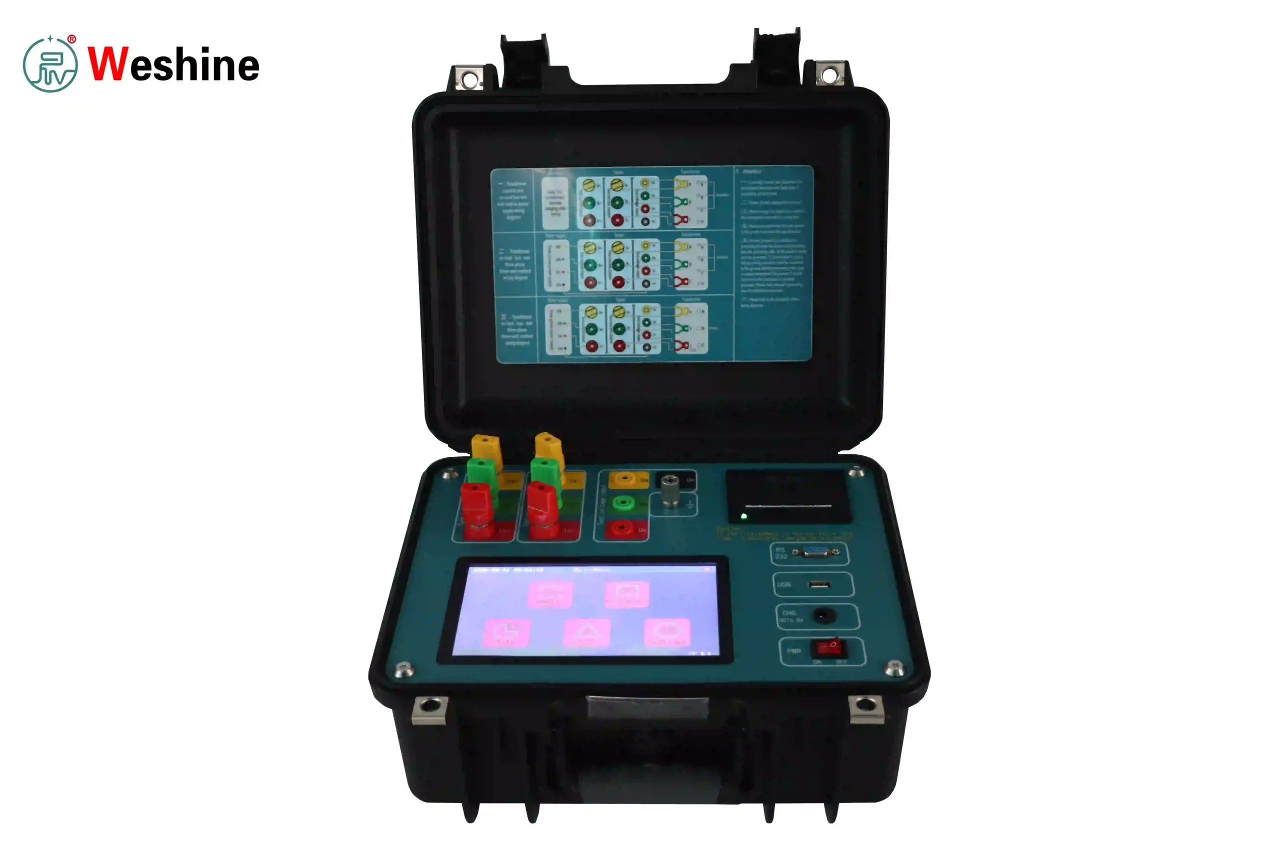
Transformer Load No Load Loss Tester & Capacity Analyzer
The Transformer Load No Load Loss Tester is a diagnostic system engineered for measuring no-load loss (P0), no-load current (I0%), load loss (Pk), short-circuit impedance voltage (Uk%), and operating efficiency in power and distribution transformers.
During Factory Acceptance Testing (FAT) in manufacturing facilities or preventive maintenance in utility substations, electrical loss measurement supports energy performance verification, quality grading, and compliance under standards such as IEC 60076 and IEEE C57.12.
Equipped with high-precision sampling hardware, this equipment provides active capacity testing, real-time waveform analysis, harmonic evaluation, and automated parameter corrections for field and laboratory environments.
Technical Specifications & Standards Comparison
The table below details the measurement capabilities and compliance standards of the loss testing series:
| Parameter / Feature | Technical Specification Range | Applicable Testing Standards |
| Voltage Measurement Range | Direct Input: 0 to 1000 V AC (Expandable via PT) | IEC 60076-1 / GB 1094.1 |
| Current Measurement Range | Direct Input: 0 to 100 A AC (Expandable via CT) | IEC 60076-8 / GB/T 6451 |
| Power Measurement Accuracy | ±0.5% F.S. (0.1 ≤ CosΦ ≤ 1) | ±1.0% F.S. (0.02 ≤ CosΦ ≤ 0.1) | IEEE C57.12.00 / IEEE C57.12.90 |
| Loss Measurement Accuracy | No-Load & Load Loss: ±2.0% reading accuracy | IEC 60076-18 / GB 1094.5 |
| Frequency Measurement | 45 Hz to 65 Hz (Resolution: 0.001 Hz) | DL/T 911 / JB/T 3837 |
| Temperature Correction Range | Standard conversions to 75°C, 100°C, 115°C, or 145°C | IEC 60076-1 Clause 10 |
| Harmonic Measurement | 2nd to 51st order voltage/current spectrum analysis | IEEE 519 / IEC 61000-4-7 |
Core Technical Features
1. Measurement Under Low Power Factor Conditions
Transformer no-load testing operates under low power factors (CosΦ ≤ 0.1). The instrument integrates multi-channel synchronous sampling and phase-compensated sampling hardware to maintain power measurement accuracy down to CosΦ = 0.02.
2. Integrated Power Source for Field Verification
Selected models feature an internal three-phase 50 Hz AC test source. This enables field engineers to perform active capacity identification and short-circuit load tests without external induction regulators, three-phase generators, or current boosters.
3. Automated Parameter Corrections
Test results are automatically converted to standard reference conditions:
-
Temperature Correction: Converts measured load losses and short-circuit impedance to standard reference temperatures (75°C or 115°C).
-
Waveform Distortion Correction: Adjusts no-load losses measured under distorted power supply waves back to true sinusoidal values.
-
Non-Rated Parameter Correction: Converts loss values tested under non-rated voltage or current to rated operating values.
4. Safety Protection and Data Export
Equipped with overvoltage, overcurrent, and phase-short circuit protection circuits. Test records are stored in an internal database and can be exported via USB, RS232, Bluetooth, or WiFi for data management and report generation.
Application Scenarios
Transformer Manufacturing & Factory Testing
-
Routine Production Inspection: Verification of core no-load loss and winding copper loss during transformer assembly.
-
Compliance Verification: Testing design parameters for oil-immersed, dry-type, and amorphous alloy transformers to verify energy-efficiency classes.
Power Utilities & Grid Maintenance
-
Distribution Asset Verification: Verifying transformer nameplate specifications and installed capacity on site.
-
Post-Repair Diagnostics: Assessing core condition or winding displacement following short-circuit faults or maintenance.
Industrial Facilities & Testing Laboratories
-
Industrial Energy Audits: Evaluating transformer operating efficiency in manufacturing, mining, and petrochemical facilities.
-
Third-Party Inspection: Providing test records and diagnostic reports using traceable measurement methods.
Functional Capabilities
Measures no-load loss (P0), no-load current percentage (I0%), load loss (Pk), short-circuit impedance voltage (Uk%), and active/reactive power with a direct input range up to 1000 V AC and 100 A AC. The system supports Single-phase, Two-wattmeter, and Three-wattmeter wiring methods while displaying real-time waveforms, vector diagrams, and 2nd–51st harmonic spectrums on a touchscreen display.
To evaluate additional substation assets, users can review our broader catalog of transformer test equipment.
Engineering Capabilities & Quality Assurance
Weshine Electric manufactures high-voltage diagnostic systems under ISO-certified quality management frameworks. Every instrument undergoes routine factory calibration, high-voltage insulation verification, and electromagnetic compatibility testing to comply with international standards such as IEC and IEEE.
As a specialized Electrical Testing Equipment Supplier, Weshine Electric supports power utilities, transformer manufacturers, and industrial facilities worldwide by providing complete diagnostic systems, traceable calibration documentation, and long-term technical service.