






Earth Resistance Tester
Searching for a high-precision earth resistance tester to verify the grounding safety of your power infrastructure? Weshine Electric is a professional manufacturer of electrical testing and power system diagnostic equipment. Our digital earth resistance testers and ground bond testers deliver fast, stable, and highly repeatable measurements of grounding resistance, soil resistivity, and ground connection continuity. Ensure low-resistance paths for fault current dissipation and satisfy international safety standards. Explore our catalog or browse our combined insulation resistance tester category.
Need technical specifications or direct factory pricing?
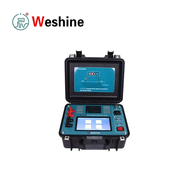
Earth Resistance Tester & Ground Grid Diagnostic Solutions
Grounding systems are fundamental to the safety and operational integrity of electrical infrastructure. In power utilities, high-voltage substations, and industrial installations, a low-resistance earthing system ensures that high lightning surges and short-circuit fault currents dissipate safely into the ground without exposing personnel to step and touch voltage hazards. Over time, soil corrosion, mechanical disconnects, and ground grid aging degrade earthing performance.
As a trusted manufacturer of electrical testing equipment, Weshine Electric develops high-precision earth resistance testers and ground bonding diagnostic instruments. Engineered with multi-electrode testing methods, advanced digital signal filtering, and intuitive user interfaces, our testers enable engineers to evaluate grounding electrode integrity, verify bonding continuity, and ensure full compliance with electrical safety codes.
Applications of Earth Resistance Testers
Power Utilities, Substations & Generating Plants
-
Substation Ground Grid Audits: Measuring the total impedance of large substation earthing networks to ensure safe fault dissipation.
-
Commissioning of New Earthing Rods: Verifying low resistance values on newly installed ground rods, tower bases, and transformer neutrals.
-
Routine Safety Compliance: Conducting periodic ground integrity inspections across transmission and distribution line footings.
Industrial Facilities & Commercial Installations
-
Equipment Bond Continuity: Testing protective earth (PE) connections on machinery frames, distribution boards, and heavy industrial enclosures.
-
Lightning Protection Systems: Verifying earth termination resistance for building lightning rods and surge protection devices.
Telecommunications & Infrastructure
-
Cell Tower Grounding Audits: Measuring ground rod impedance at remote communication sites to protect sensitive radio and network hardware.
-
Data Center Safety Inspection: Verifying low-impedance earthing networks to prevent static discharge and equipment noise.
Featured Grounding Testing Products
Explore our specialized field diagnostic instrument designed for ground bonding and continuity verification:
10A Ground Bond Tester
Designed for high-precision ground bonding and protective conductor resistance measurement using a continuous 10A DC test current. Features milliohm (mΩ) resolution, automated testing procedures, and digital result reporting.
-
Test Current Output: 10A DC regulated test current for high-accuracy low-resistance measurements.
Core Technical Significance of Ground Resistance Testing
Accurate earth testing requires assessing both localized connection continuity and overall ground dissipation impedance:
Utilizing a digital earth resistance tester with active frequency selection prevents stray AC ground currents and station noise from corrupting measurement accuracy during live substation audits.
Key Features and Engineering Technology
Multi-Electrode Diagnostic Capability
Supports 2-wire, 3-wire, and 4-wire fall-of-potential testing methods, as well as soil resistivity (4-point method) measurements, adapting to diverse site ground configurations.
Advanced Digital Noise Filtering
Features micro-processor digital filtering that filters out power frequency (50 Hz / 60 Hz) interference and ground stray currents, delivering stable resistance readings even in high-voltage electromagnetic environments.
Automated Calculation & Data Management
Equipped with clear digital display screens, automatic range selection, internal memory storage, and data export options to streamline site report generation.
Portable & Rugged Field Enclosure
Designed with heavy-duty weather-sealed cases and high-capacity rechargeable batteries, ideal for extended outdoor field operations across harsh utility landscapes.
Advantages of Weshine Earth Resistance Testers
-
High Precision & Repeatability: Delivers stable readings with accuracy held strictly within ±1% for reliable condition tracking over time.
-
Fast & Simple Operation: Automated test routines eliminate manual balancing, enabling rapid multi-point field measurements.
-
Comprehensive Operator Safety: Features overvoltage, overcurrent, and open-circuit automatic protection for maximum operator safety during testing.
-
Versatile Industry Application: Suitable for everything from low-resistance grounding bonds (mΩ range) to deep ground electrode networks.
International Grounding & Safety Standards
How to Select the Right Earth Testing Instrument
When selecting an earth resistance tester or ground bond set, evaluate these key criteria:
-
Test Method Compatibility: Ensure the instrument supports 3-wire / 4-wire fall-of-potential for ground rods, or high-current DC (such as 10A) for ground continuity.
-
Current Output Level: For equipment grounding bond tests, high-current injection (10A DC) breaks through surface oxidation for accurate micro-resistance readings.
-
Integrated Electrical Safety Fleet: Pair your ground testing tools with an insulation resistance tester from our broader line of Electrical Testing Instruments for complete safety commissioning.
Why Choose Weshine Electric
Manufacturer Direct Quality & Expertise
Weshine Electric specializes in power testing and diagnostic equipment. With strong engineering capability and strict quality control, we deliver earth resistance testers that perform reliably under challenging field conditions.
Comprehensive Power Diagnostic Lineup
We offer complete diagnostic suites including ground bond testers, high-voltage megohmmeters, transformer test equipment, and underground cable fault locators.
Global B2B Sales & Technical Support
We serve power utilities, contractors, and industrial plants worldwide with technical consultation, calibration support, OEM/ODM solutions, and direct factory pricing.
Frequently Asked Questions
Q1: What is an earth resistance tester used for?
An earth resistance tester measures the electrical resistance between a grounding electrode (or ground grid) and the surrounding earth. It verifies that grounding installations provide a low-resistance path to dissipate fault currents safely into the ground.
Q2: What is the difference between an earth resistance test and a ground bond test?
An earth resistance test measures the resistance of the ground electrode/grid to soil (in ohms), while a ground bond test (using a tool like a 10A ground bond tester) measures the metallic continuity resistance (in milliohms) between equipment frames and the main ground grid.
Q3: What is a safe or acceptable ground resistance value?
For main power substations, ground grid resistance is typically required to be under 1.0 ohm (often under 0.5 ohm). For commercial or industrial equipment grounding, standard electrical codes generally require resistance values under 5.0 ohms.
Q4: Why is a 4-wire measurement method preferred for ground resistance testing?
The 4-wire (Kelvin) measurement method eliminates the test lead resistance and contact resistance from the measurement result, enabling precise evaluation of extremely low grounding and bonding resistance values.