






How to Test a Current Transformer Before Commissioning and During Service?
September 30, 2026
How do you test a current transformer accurately and safely? The usual process combines visual inspection, winding resistance measurement, insulation testing, excitation testing, polarity verification, ratio testing, and phase or burden checks. The exact sequence depends on the CT type, voltage class, application, and applicable testing standard.
For utilities, substations, transformer manufacturers, and electrical testing contractors, CT testing serves a practical purpose. It confirms whether the current transformer can provide the expected secondary signal to protection and metering systems.
A CT can appear mechanically intact while still having an incorrect ratio, polarity issue, excessive excitation current, or winding resistance problem. These conditions can affect relay operation and measurement accuracy.
Consider a protection CT installed on a medium-voltage feeder. The primary conductor carries the expected current, but the secondary ratio differs from the design value. The protection relay may then receive an incorrect current signal. During a fault, that error can affect relay response.
For this reason, a proper CT test should not focus on only one parameter. Engineers normally combine several measurements and compare the results with nameplate data, factory records, previous field results, and applicable standards.
What Does Current Transformer Testing Check?
A current transformer reduces a large primary current to a smaller secondary current for measurement and protection. Its performance depends on its ratio, winding condition, magnetic core, insulation, polarity, and connected burden.
Testing verifies these characteristics before the CT enters service and during its operating life.
Current Transformer Ratio
The current transformer ratio defines the relationship between primary and secondary current.
For example, a CT rated at 600/5 A should produce approximately 5 A on the secondary when the primary carries 600 A under the specified conditions.
Ratio testing helps verify that the installed CT matches the required protection or metering design.
A ratio error may result from incorrect winding configuration, connection mistakes, manufacturing issues, or other conditions. Engineers should compare measured values with the applicable accuracy requirements.
Polarity
CT polarity determines the phase relationship between primary and secondary currents.
Incorrect polarity can cause serious issues in differential protection, directional protection, and other protection schemes.
For example, two CTs connected to a differential relay must produce compatible current directions. If one CT has reversed polarity, the relay may interpret normal load current incorrectly.
Polarity testing should therefore form part of the commissioning process.
Excitation Characteristics
Excitation testing evaluates the relationship between applied secondary voltage and excitation current.
The resulting curve provides information about the magnetic behavior of the CT core.
Engineers often examine the knee point for protection-class CTs. The knee point helps assess whether the CT can maintain suitable performance during fault conditions.
A CT with excessive excitation current may require further investigation. The cause can relate to the magnetic core, winding condition, residual magnetism, or other factors.
Winding Resistance
Secondary winding resistance provides information about the electrical continuity and condition of the CT winding.
A significant difference between comparable CTs may indicate a connection issue, winding problem, or measurement condition that requires investigation.
Temperature affects winding resistance, so test records should include relevant temperature information.
Insulation Condition
Insulation tests assess the electrical separation between windings and ground.
The exact test method depends on the CT design and insulation system.
Testing teams should follow the applicable standard and equipment manufacturer’s instructions. They should also confirm that connected devices can safely withstand the selected test voltage.
Which Tests Should Be Performed on a Current Transformer?
A complete CT test program depends on the application.
Protection CTs, metering CTs, bushing CTs, and multi-ratio CTs can have different requirements. A factory acceptance test may also cover more parameters than a routine field inspection.
The following table summarizes common tests.
| Test | Main Purpose | Typical Application |
|---|---|---|
| Ratio test | Verify transformation ratio | Protection and metering CTs |
| Polarity test | Verify phase relationship | Protection and metering |
| Excitation test | Evaluate magnetic core behavior | Protection CTs |
| Knee-point test | Identify core saturation characteristics | Protection CTs |
| Winding resistance | Check winding and connections | Most CT types |
| Insulation resistance | Assess insulation resistance | Field and maintenance testing |
| Burden test | Verify connected load conditions | Metering and protection |
| Demagnetization | Reduce residual magnetism | After excitation testing |
| Secondary injection | Verify connected protection circuits | Protection systems |
A testing engineer should define the test scope before connecting the instrument.
The goal is not to perform every available measurement on every CT. The goal is to verify the parameters that matter for the intended application.
How to Test a Current Transformer Step by Step?
A structured test procedure reduces connection errors and improves repeatability.
Before starting, technicians should review the CT nameplate, drawings, wiring diagrams, previous test reports, and relevant protection settings.
Step 1: Confirm CT Nameplate Data
Record the key information before connecting the test instrument.
Typical information includes:
- Primary current rating
- Secondary current rating
- Accuracy class
- Rated burden
- Frequency
- Number of cores
- Core designation
- Insulation level
- Ratio taps
- Protection class or metering class
Multi-ratio CTs require particular attention because the selected tap changes the effective ratio.
Step 2: Isolate the CT
The CT must be isolated according to the site’s approved safety procedure.
One important rule applies to energized CT secondary circuits: never leave a CT secondary open while primary current flows.
An open CT secondary can generate a dangerous voltage. This voltage can damage equipment and create a serious electrical hazard.
Before disconnecting a secondary circuit, confirm the primary condition and use the approved shorting arrangement.
Step 3: Inspect the Physical Condition
Inspect terminals, wiring, nameplates, grounding connections, insulation surfaces, and enclosure conditions.
Look for loose connections, corrosion, physical damage, contamination, or signs of overheating.
The inspection can reveal installation problems before electrical testing begins.
Step 4: Measure Winding Resistance
Connect the tester to the appropriate CT secondary winding.
Apply the test current according to the instrument’s procedure. Allow the reading to stabilize before recording the result.
For multi-core CTs, test each relevant winding separately.
Compare results between phases or equivalent CTs when appropriate.
Step 5: Perform Ratio Testing
Ratio testing verifies the relationship between primary and secondary circuits.
For a 1000/5 A CT, the nominal ratio equals 200:1.
The tester applies the required test signal and calculates the measured ratio.
Engineers should compare the result with the CT nameplate and specified accuracy class.
A ratio deviation may indicate an incorrect tap connection, winding issue, connection error, or other abnormal condition.
Step 6: Check Polarity
Polarity testing verifies the relative direction of primary and secondary current.
The test becomes particularly important for differential and directional protection.
Technicians should verify polarity at the CT terminals and compare the result with the protection wiring diagram.
Step 7: Perform Excitation Testing
For suitable protection CTs, the test instrument applies increasing secondary voltage while measuring excitation current.
The resulting excitation curve shows how the magnetic core responds to increasing voltage.
The knee point can then be determined according to the applicable definition and testing method.
This information helps engineers assess the CT’s ability to support protection functions during fault conditions.
Step 8: Demagnetize the Core
Excitation testing can leave residual magnetism in the CT core.
Residual magnetism can affect subsequent measurements and CT performance.
Many modern test instruments therefore provide a demagnetization function after excitation testing.
The procedure should follow the test equipment manufacturer’s instructions.
Step 9: Review and Document Results
A complete report should identify the CT and record the test conditions.
Important information includes:
- CT identification
- Test date
- Test temperature
- CT ratio
- Test tap
- Test method
- Measured ratio
- Winding resistance
- Excitation results
- Polarity
- Insulation results
- Final assessment
Historical records make future troubleshooting easier.
How Do CT Test Results Affect Protection and Metering?
Current transformers serve different purposes, so test interpretation must reflect the application.
Protection CTs must provide suitable current signals during abnormal system conditions. Their magnetic behavior becomes important when fault current causes the core to approach saturation.
Metering CTs focus on measurement accuracy under specified operating conditions.
Protection CT Example
Imagine a substation uses a 1200/5 A protection CT.
The relay expects a specific secondary current corresponding to the primary fault current. If the CT saturates too early, the secondary waveform may no longer represent the primary current accurately.
The relay may then receive a distorted signal.
An excitation test can help identify whether the CT’s magnetic characteristics align with the protection design.
Metering CT Example
Now consider a 600/5 A metering CT connected to an energy meter.
A ratio error can affect current measurement and therefore energy calculations.
The acceptable error depends on the CT’s specified accuracy class and operating conditions.
The same CT test method cannot therefore be interpreted identically for protection and metering applications.
What Equipment Is Needed to Test a Current Transformer?
A professional CT testing setup usually combines several measurement functions into one coordinated test process.
A basic field kit may include a suitable CT analyzer, test leads, grounding accessories, shorting equipment, and safety equipment.
For larger testing programs, an integrated system can simplify the workflow.
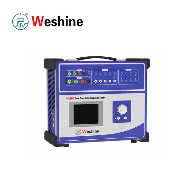
A Current Transformer Analyzer can perform multiple measurements such as ratio, excitation, winding resistance, polarity, and related CT parameters.
A broader current transformer testing system can support CT and PT testing within a unified instrument platform.
What Should Buyers Consider?
For utilities and testing contractors, equipment selection should focus on technical requirements rather than the number of functions listed in a brochure.
Important factors include:
- Supported CT classes and ratios
- Excitation voltage range
- Ratio measurement accuracy
- Winding resistance test range
- Demagnetization capability
- Test report generation
- Data storage
- Field portability
- Connection protection
- Compatibility with the intended test workflow
The required specification should come from the actual CT population being tested.
A contractor working mainly with distribution CTs may have different requirements from a utility testing high-voltage protection CTs.
Contact WESHINE to discuss CT testing equipment requirements for your application.
How Should a CT Testing System Be Selected for Different Applications?
A single test platform may serve several applications, but engineers should verify the actual operating range before purchase.
Substation Commissioning
Commissioning teams often need ratio, polarity, winding resistance, excitation, and insulation-related testing.
Portability can also matter because technicians may need to test multiple CTs within a short outage window.
Transformer Testing
Power transformers often contain multiple CTs integrated into bushings or neutral systems.
The test plan should account for the CT location, accessible terminals, ratio configuration, and protection function.
Protection Relay Testing
Protection engineers may need CT data alongside relay settings.
The test system should allow results to transfer into commissioning documentation and protection test records.
Manufacturer Factory Testing
Manufacturers may require more controlled testing conditions.
Repeatability, data management, and test reporting become particularly important when many units undergo similar procedures.
Field Service and Maintenance
Maintenance contractors often work with CTs of different ratings and manufacturers.
A flexible instrument transformer test system can reduce the need for separate equipment across different test tasks.
What Common Mistakes Should Be Avoided During CT Testing?
CT testing can produce incorrect results when the test setup does not match the equipment configuration.
One common mistake involves using the wrong CT ratio or tap information.
A second mistake occurs when technicians overlook the difference between protection and metering cores.
Another issue involves failing to document temperature during winding resistance testing.
Incorrect grounding can also introduce measurement errors or create safety hazards.
Finally, technicians sometimes interpret test results without checking historical records.
A measurement should always be considered alongside the CT nameplate, applicable standards, manufacturer data, and previous test results.
Practical Checklist Before Testing
Before applying a test signal, confirm:
- The correct CT has been identified.
- The test tap matches the test plan.
- The secondary circuit is isolated correctly.
- The CT secondary is never left open during energized primary operation.
- Connected equipment has been disconnected where required.
- Test leads match the selected measurement.
- Grounding follows the approved procedure.
- The test voltage remains within the specified limits.
This preparation often prevents more problems than additional testing functions can solve.
How Can Utilities Improve CT Testing Records?
A consistent record structure helps utilities compare CT performance across years.
Each CT should have a unique identification number linked to its location and protection or metering function.
Test reports should preserve both raw measurements and calculated results.
For example, a utility can compare the winding resistance of the same CT during commissioning and later maintenance.
A noticeable change may justify investigation even when the latest measurement still falls within a general reference range.
Trend information becomes particularly useful when engineers manage large fleets.
Digital reporting also reduces transcription errors. It allows test data to remain connected with equipment records and maintenance history.
FAQ About Current Transformer Testing
Why do current transformers need testing?
CT testing verifies key characteristics such as ratio, polarity, winding resistance, and magnetic performance. These characteristics affect protection and measurement accuracy.
What is the most important CT test?
There is no single test that covers every CT application.
Ratio and polarity are fundamental commissioning checks. Excitation testing becomes particularly important for protection CTs.
How do you test a CT ratio?
A CT analyzer applies a controlled test signal and measures the corresponding primary and secondary relationship. The measured ratio is then compared with the nameplate and required accuracy.
What is the purpose of a CT excitation test?
An excitation test evaluates the magnetic behavior of the CT core. Engineers can use the resulting curve to assess saturation characteristics and related protection performance.
Why is CT polarity important?
Polarity determines the phase relationship between primary and secondary currents. Incorrect polarity can affect differential, directional, and other protection schemes.
Can a multimeter test a current transformer?
A multimeter can perform limited continuity or resistance checks. It cannot replace a dedicated CT test system for ratio, excitation, polarity, and comprehensive diagnostic testing.
What is CT saturation?
CT saturation occurs when the magnetic core can no longer maintain the expected relationship between applied secondary voltage and magnetizing behavior.
During high fault currents, saturation can distort the secondary current waveform.
What is the difference between a CT analyzer and CT test equipment?
A CT analyzer usually integrates several CT-specific measurement functions.
The broader term CT PT test equipment can refer to equipment designed for testing both current transformers and potential or voltage transformers.
Can CT testing be performed in the field?
Yes. Many modern CT test systems support field testing.
The testing team must still follow the required isolation, grounding, safety, and connection procedures.
How often should current transformers be tested?
The interval depends on the application, asset importance, operating environment, maintenance program, and applicable standards.
Commissioning and post-maintenance testing may also occur outside the normal maintenance interval.
References
- IEC, IEC 61869-1, Instrument Transformers, General Requirements:
https://webstore.iec.ch/en/publication/60130 - IEC, IEC 61869-2, Instrument Transformers, Additional Requirements for Current Transformers:
https://webstore.iec.ch/en/publication/60248 - IEEE, IEEE Std C57.13, Standard Requirements for Instrument Transformers:
https://standards.ieee.org/ieee/C57.13/1057/ - IEEE, IEEE Std C37.110, Guide for the Application of Current Transformers Used for Protective Relaying Purposes:
https://standards.ieee.org/ieee/C37.110/1029/ - National Institute of Standards and Technology, Electrical Measurements and Instrumentation Resources:
https://www.nist.gov/
WESHINE develops electrical testing equipment for power systems, substations, transformers, and instrument transformers. Its testing solutions support CT and PT measurement, insulation testing, and related high-voltage diagnostic applications. For utilities, transformer manufacturers, testing contractors, and industrial users, WESHINE provides equipment designed around practical field and laboratory testing requirements.

