






How Do You Perform a Transformer Turns Ratio (TTR) Test According to IEEE and IEC Guidelines?
October 14, 2026
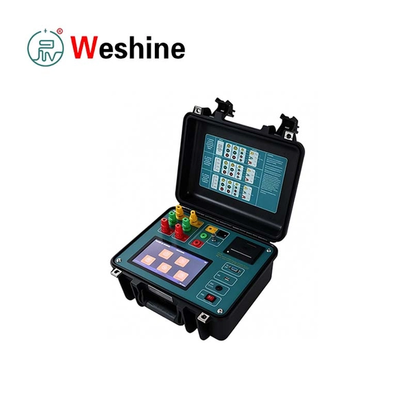
To perform a transformer turns ratio (TTR) test, technicians apply a controlled AC test voltage to one winding and measure the corresponding voltage on another winding. They then compare the measured ratio with the transformer’s rated ratio, accounting for tap position, winding configuration, and phase displacement. A reliable procedure also requires safe isolation, correct lead connections, suitable test equipment, and consistent interpretation of results. IEEE and IEC standards provide relevant guidance for transformer testing, but the applicable document depends on the transformer type, test purpose, and project requirements. For maintenance teams, commissioning engineers, and testing service providers, a suitable Transformer Tester helps identify ratio errors, tap-changer problems, and certain winding connection issues before equipment returns to service.
For example, a transformer with a rated ratio of 10:1 should produce approximately the expected voltage ratio under the specified test conditions. A significant deviation may indicate an incorrect tap position, connection error, winding problem, or unsuitable test setup. Technicians should investigate the cause before accepting the result.
1. What Does a Transformer Turns Ratio Test Measure?
A TTR test verifies the relationship between the voltage turns of a transformer’s windings. For an ideal transformer, the voltage ratio corresponds to the turns ratio. In practical testing, the instrument measures the voltage ratio and evaluates it against the rated values and specified acceptance criteria.
Why TTR Testing Matters
The turns ratio affects the voltage transformation between the primary and secondary windings. An incorrect ratio can lead to unsuitable output voltage and may indicate a manufacturing, connection, or maintenance issue.
TTR testing supports several activities:
- Factory acceptance testing before shipment.
- Commissioning checks before energization.
- Maintenance after repairs or winding work.
- Tap-changer verification following adjustments.
- Diagnostic investigations after abnormal operating results.
- Periodic condition assessment where the maintenance plan requires it.
The test can identify ratio deviations and help reveal incorrect winding connections or tap positions. However, it cannot independently establish the complete condition of a transformer. Insulation resistance, winding resistance, power factor, and other tests may be necessary for a broader assessment.
Basic Transformer Turns Ratio Formula
For an ideal transformer, the turns ratio follows the voltage ratio:
N₁ / N₂ ≈ V₁ / V₂
Where:
- N₁ is the number of turns in the first winding.
- N₂ is the number of turns in the second winding.
- V₁ is the voltage across the first winding.
- V₂ is the voltage across the second winding.
For example, a transformer rated at 11,000 V on the high-voltage side and 440 V on the low-voltage side has a nominal line-voltage ratio of 25:1. A TTR instrument may use winding-specific connections and compensation to evaluate the expected ratio for the selected phase and configuration.
Technicians must distinguish the line-voltage ratio from the phase-winding turns ratio. Delta and star connections can introduce different relationships between line and phase voltages. The instrument’s connection settings and the manufacturer’s test procedure must account for these differences.
What a TTR Test Cannot Confirm
A normal ratio result does not prove that every transformer component operates correctly. The test does not replace checks for insulation deterioration, excessive winding resistance, moisture, or other defects.
A useful diagnostic program combines TTR results with nameplate verification, visual inspection, and other relevant electrical tests. Engineers should interpret results against the transformer’s baseline data whenever available.
2. Which IEEE and IEC Standards Apply to Transformer Turns Ratio Testing?
TTR procedures should follow the applicable standard, transformer specification, and test instrument manual. IEEE and IEC documents address transformer testing from different perspectives. Neither should be treated as a universal substitute for the manufacturer’s acceptance criteria.
IEEE Guidance for Field Testing
IEEE C57.152 provides guidance for diagnostic field testing of liquid-filled power transformers, regulators, and reactors. The current edition is IEEE C57.152-2025, which supersedes the 2013 edition. It discusses field measurements, diagnostic interpretation, and the need to assess multiple test results together.
For TTR testing, the relevant principles include:
- Compare measured voltage ratios with the nameplate and expected winding configuration.
- Check ratio, polarity, and phase relationships before first energization.
- Consider tap position when recording and interpreting results.
- Investigate deviations alongside other diagnostic findings.
- Follow manufacturer criteria when they govern acceptance for the specific transformer.
IEEE guidance is especially relevant to maintenance teams and commissioning engineers working with liquid-filled power transformers. Other transformer types may require additional standards or project-specific procedures.
IEC Guidance for Power Transformer Testing
IEC 60076-1 addresses general requirements for power transformers. It covers ratings, connection symbols, tapped windings, nameplate information, and specified tests. The IEC publication record identifies the 2011 edition as a later version of the earlier 1993 publication.
When applying IEC requirements, technicians should check the contractually specified edition and any applicable amendments. The test plan should use the transformer’s declared voltage ratings and winding connections to determine the expected ratio.
For international projects, procurement teams should confirm which standards apply to the transformer and its acceptance process. A specification may cite IEC requirements, IEEE guidance, local regulations, or a combination of documents.
How Should Buyers Interpret Ratio Tolerance?
A ratio tolerance defines the permitted difference between the measured ratio and the expected value. The applicable acceptance limit depends on the governing standard, transformer design, contractual specification, and test method.
Do not assume one tolerance applies to every transformer and every tap. IEEE field-testing guidance discusses a 0.5% ratio criterion in its relevant context, but technicians must confirm the applicable edition and conditions before using that value.
The acceptance procedure should state:
- Which nameplate ratio or calculated reference value applies.
- Whether the comparison uses phase or line voltages.
- How vector group and winding connections affect the expected result.
- Which tolerance applies to each winding and tap.
- How the team should handle borderline or inconsistent measurements.
A measurement outside the specified limit requires investigation. It does not automatically identify the failed component or establish the root cause.
3. What Transformer Testing Equipment Is Required Before Starting a TTR Test?
The test setup should match the transformer’s electrical configuration and the required measurement range. Suitable transformer testing equipment helps technicians measure ratios consistently while reducing wiring errors and recording mistakes.
Choose the Appropriate Transformer Test Set
A Transformer Test Set designed for TTR measurements typically applies a controlled test signal and measures the resulting winding voltage relationship. Depending on the model, it may also assess phase displacement, polarity, excitation current, and other parameters.
Before selecting a unit, verify the following capabilities:
- Supported transformer types and winding configurations.
- Single-phase or three-phase testing modes.
- Available test voltage and measurement range.
- Supported vector groups and tap configurations.
- Ratio accuracy and repeatability specifications.
- Lead identification and connection guidance.
- Data storage, reporting, and export functions.
- Calibration status and required maintenance.
A basic instrument may suit routine distribution transformer checks. Complex transformers with multiple windings, unusual vector groups, or extensive tap ranges may require more advanced functions.
Single-Phase Versus Three-Phase Testing
A single-phase TTR instrument tests one phase or winding relationship at a time. This approach can suit many applications, provided technicians use the correct connection procedure and account for the transformer vector group.
A three-phase transformer test system can measure multiple phase relationships in a coordinated sequence. Depending on its design, it may reduce connection time and help compare phase results more efficiently.
However, the instrument must support the actual transformer configuration. Delta-connected windings and complex phase relationships require particular care. A three-phase instrument does not eliminate the need for correct connections or interpretation.
For example, a maintenance team testing a three-phase distribution transformer may prefer automated three-phase measurements when the instrument supports its vector group. A team testing a simple single-phase transformer may not need those additional functions.
Prepare the Test Leads and Documentation
Before connecting the instrument, review the transformer nameplate, wiring diagram, previous test records, and manufacturer’s instructions. Confirm the terminal labels and identify the high-voltage and low-voltage windings.
Inspect the test leads for damaged insulation, loose connectors, contamination, and unclear labels. Confirm that the instrument has a valid calibration status under the organization’s quality system.
A useful test record includes:
- Transformer manufacturer, serial number, and rated power.
- Rated voltages and winding configuration.
- Vector group and nameplate ratio.
- Tap-changer type and selected position.
- Instrument model, serial number, and calibration details.
- Test date, ambient conditions where relevant, and operator.
- Individual phase readings and acceptance results.
These records allow engineers to compare future measurements against a reliable baseline.
4. How Do You Perform a Transformer Turns Ratio Test Step by Step?
A controlled procedure improves repeatability and helps prevent incorrect conclusions. The steps below describe a general workflow. The instrument manual and the site’s approved safety procedures take precedence whenever they specify different requirements.
Step 1: Isolate and Secure the Transformer
Disconnect the transformer from all power sources before testing. Apply the site’s lockout/tagout procedure and verify the absence of voltage using approved methods.
Follow the organization’s grounding and discharge procedures. Account for auxiliary supplies, induced voltages, backfeed, and any connected circuits that could create hazards.
Only qualified personnel should perform transformer testing. A low-voltage test signal does not make an inadequately isolated transformer safe to handle.
Step 2: Confirm the Nameplate and Tap Position
Record the rated voltage of each winding, the vector group, and the nameplate ratio. Identify the tap position and confirm whether the procedure requires testing in the as-found position or at every available tap.
For a de-energized tap changer, verify that the transformer is isolated and that the tap mechanism can be operated safely. Follow the manufacturer’s instructions when moving between positions.
On commissioning projects, the test plan may require measurements across the full tap range. Maintenance procedures may also require an initial as-found measurement before any adjustment.
Step 3: Connect the Transformer Tester
Connect the test leads to the specified winding terminals according to the instrument’s wiring diagram. Check the phase labels and polarity markings carefully.
Do not rely on terminal positions alone. Different vector groups use different winding connections, and similar-looking transformers may have different terminal arrangements.
Review the instrument’s displayed connection diagram before starting the measurement. Correct any lead mismatch or configuration warning before continuing.
Step 4: Enter the Transformer Parameters
Enter the rated voltages, winding configuration, vector group, and tap information when the instrument requires them. Some devices calculate the expected ratio from this data.
Incorrect parameters can produce misleading pass/fail results even when the raw measurement is repeatable. Check the entries against the nameplate and the approved test sheet.
If the instrument uses a predefined transformer template, confirm that its configuration matches the unit under test.
Step 5: Run the TTR Measurement
Start the test according to the instrument instructions. The Transformer Tester applies its controlled test signal and calculates the measured voltage ratio.
Observe the instrument’s status messages and any connection warnings. Record the displayed ratio and additional parameters available for the selected mode.
Do not touch test leads or change connections while the instrument is applying its test signal. Follow the specified shutdown procedure before moving the leads.
Step 6: Test Each Required Phase and Tap
Measure all phases and winding combinations required by the test plan. For tapped transformers, test the positions specified by the acceptance or maintenance procedure.
Keep the records organized by phase, winding, and tap position. This structure helps reveal isolated deviations and trends across the full range.
For example, a transformer may show acceptable ratios on most taps but an unexpected deviation on one position. That pattern warrants a focused investigation of the tap setting, connections, and related components.
Step 7: Review and Save the Results
Compare each reading with the expected ratio and the applicable acceptance criteria. Confirm that the instrument used the correct winding configuration and reference values.
Save the readings with the transformer identification and test conditions. Document any warnings, unusual excitation behavior, or repeated measurements.
If results appear inconsistent, verify the connections and input parameters before assuming an internal defect. Repeat the measurement only after identifying and correcting a plausible source of error.
For routine field work, a dedicated TTR Tester can help technicians perform repeatable measurements across different transformer types, provided its specifications match the application.
If you are selecting a test instrument for commissioning, maintenance, or transformer manufacturing, contact WESHINE for guidance on suitable TTR testing equipment and measurement requirements.
5. How Should Engineers Calculate and Interpret TTR Results?
A correct measurement is only useful when the team compares it with the correct reference value. Engineers should review ratio deviation, phase consistency, tap progression, and any instrument warnings before accepting the transformer.
Calculate the Ratio Deviation
A common way to express the percentage deviation is:
Ratio Deviation (%) = [(Rₘ − Rₑ) / Rₑ] × 100
Where:
- Rₘ is the measured ratio.
- Rₑ is the expected ratio calculated from the applicable reference values.
The sign indicates whether the measured ratio is above or below the reference. Some instruments display deviation using a different sign convention, so technicians should verify the manual before comparing reports.
For example, assume the expected ratio is 25.00 and the measured ratio is 25.08.
[(25.08 − 25.00) / 25.00] × 100 = 0.32%
The deviation is +0.32%. Whether this result passes depends on the applicable acceptance limit and the correctness of the reference calculation.
Example: Testing a Three-Phase Transformer
Consider a three-phase transformer with a high-voltage rating of 11 kV and a low-voltage rating of 440 V. Its nominal line-voltage ratio is 25:1.
If the transformer uses a delta-star connection, technicians must account for the relationship between line and phase voltages. The expected ratio for a particular measurement may therefore differ from a simple comparison of the two line ratings.
Suppose the instrument reports phase results of 25.02, 24.98, and 25.01 after applying the correct vector-group configuration. These values are close to the expected reference. Engineers should still compare each result with the applicable acceptance criteria and check the overall test record.
If one phase instead shows a substantially different ratio, technicians should verify lead connections and configuration settings first. If the deviation remains, they should investigate the winding, tap changer, and related connections.
Use a Consistent Interpretation Framework
Table 1. Common TTR test findings and recommended investigation steps
| Test finding | Possible explanation | Recommended action |
|---|---|---|
| Similar deviation on every phase | Incorrect reference data or tap setting | Verify nameplate values, configuration, and tap position |
| One phase differs significantly | Connection error or winding-related issue | Check leads, terminal labels, and phase-specific results |
| Deviation occurs at one tap only | Tap contact or tap-position problem | Verify tap position and inspect according to the approved procedure |
| Readings fluctuate between tests | Poor connections or unstable setup | Inspect leads, terminals, and instrument condition |
| Phase relationship is inconsistent | Incorrect vector-group selection or connection issue | Confirm winding diagram and instrument configuration |
| Ratio passes but other tests fail | A different transformer defect may exist | Review the broader diagnostic test results |
These patterns help guide investigation but do not prove a specific fault. Engineers should combine TTR results with winding resistance, insulation testing, and other relevant measurements when necessary.
Understand Three-Phase Differences
Small differences between phase readings can arise from the winding design and measurement configuration. Engineers should compare those differences with the expected design behavior and the applicable criteria.
Do not reject a transformer solely because the three readings are not numerically identical. Instead, evaluate the magnitude, repeatability, tap position, and relationship to previous measurements.
When the instrument supports phase-angle measurement, use that information to help verify the winding connection and vector relationship. This can be especially useful when testing three-phase units or transformers with complex connections.
Know When to Escalate an Abnormal Result
Stop the acceptance process when results exceed the specified limits or remain inconsistent after connection checks. Document the deviation and follow the organization’s diagnostic procedure.
Depending on the findings, engineers may need to check winding resistance, inspect tap-changer operation, verify the nameplate data, or conduct additional diagnostic tests. Avoid repeated testing without a defined reason because it can obscure the original condition.
A transformer should return to service only after qualified personnel evaluate the results and authorize the next step under the applicable procedures.
Frequently Asked Questions
What is the purpose of a transformer turns ratio test?
A TTR test verifies the relationship between winding voltages and the expected transformer ratio. It can help identify ratio errors, incorrect tap positions, connection problems, and certain winding faults. Engineers should combine it with other tests when assessing overall transformer condition.
What equipment is needed for a TTR test?
A suitable Transformer Test Set, compatible test leads, transformer nameplate data, and the approved test procedure are essential. The instrument should support the winding configuration and measurement range. Additional documentation and safety equipment depend on the site procedure.
What is an acceptable TTR test result?
The result must satisfy the acceptance criteria defined by the applicable standard, transformer specification, and manufacturer. A 0.5% criterion appears in relevant IEEE field-testing guidance, but it should not be applied indiscriminately to every design or test condition.
Should technicians test every tap position?
The required tap positions depend on the test purpose and approved procedure. Commissioning may require measurements across the full tap range. Maintenance work may require an as-found measurement and additional checks following adjustment or repair.
Can a TTR test identify shorted turns?
A significant ratio deviation may indicate shorted turns, but the result alone does not confirm the cause. Technicians should verify the setup and compare the findings with other diagnostic tests before drawing conclusions.
What is the difference between a single-phase and a three-phase TTR Tester?
A single-phase instrument measures one winding relationship at a time. A three-phase unit can coordinate measurements across phases when its design supports the transformer configuration. The appropriate choice depends on the transformer type, required functions, and testing workflow.
Why might TTR readings differ between phases?
Differences may result from incorrect connections, configuration errors, tap positions, winding design, or internal faults. Technicians should confirm the setup first and then compare the measurements with expected phase relationships and applicable acceptance criteria.
How often should a transformer undergo TTR testing?
There is no universal interval for every transformer. Testing may form part of factory acceptance, commissioning, maintenance after repair, tap-changer checks, or an investigation following abnormal events. Asset condition and the maintenance plan should determine the schedule.
Conclusion
A reliable transformer turns ratio test combines correct connections, accurate nameplate data, suitable test equipment, and disciplined interpretation. IEEE and IEC documents provide important guidance, but technicians must apply the edition and acceptance criteria specified for the project. Recording results across the required phases and tap positions helps identify deviations and supports later condition comparisons. WESHINE develops transformer testing equipment for electrical testing professionals, including TTR instruments designed to support field and laboratory workflows. By matching the instrument to the transformer configuration and following approved procedures, testing teams can produce more consistent measurements and better-informed maintenance decisions.
References
1. IEEE SA: IEEE C57.152-2025 Current IEEE guide for diagnostic field testing of liquid-filled power transformers, regulators, and reactors.
2. IEC Webstore: IEC 60076-1, Power Transformers, Part 1: General IEC reference for general power transformer requirements, including ratings, connection symbols, and specified tests. Confirm the applicable edition and amendments for your project.
3. Megger: Transformer Turns Ratio Testing Technical overview of TTR principles, measurement functions, and field applications.
4. Megger: Transformer Turns Ratio Test, Technical Paper Discussion of ratio interpretation, vector configurations, tap positions, and sources of measurement error.

