






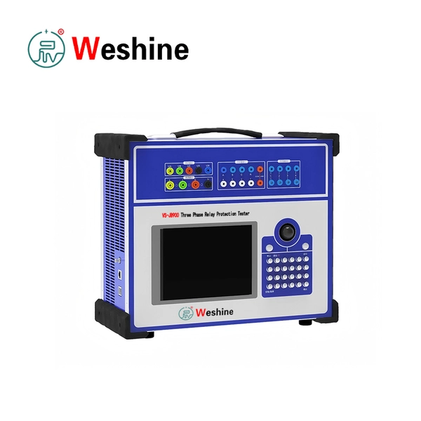

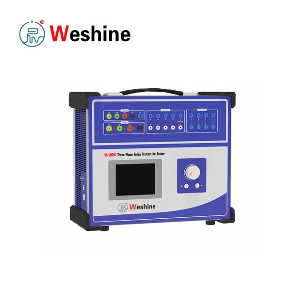
Three-Phase Relay Protection Tester | VS-JB900
Products Details
VS-JB900 Three-Phase Relay Protection Tester is engineered for comprehensive testing of protective relays, microprocessor protection devices, secondary circuits, automation equipment, and related protection schemes across power networks. Protective relay systems must perform with total accuracy during power system faults, abnormal voltage conditions, overcurrent events, reclosing sequences, differential protection operations, and control circuit actions. Regular secondary injection testing is therefore essential for maintaining safe and selective power system operation. Complementing our specialized Transformer Test Set range, this instrument delivers high-precision signal generation for full secondary circuit verification.
The tester features standard 4-phase voltage and 3-phase current outputs. The voltage channels support tests for phase voltage, line voltage, zero-sequence voltage, voltage balance, voltage loss, frequency variation, and synchronism. The three current channels can output independent phase currents or be connected in parallel for high-current output up to 120 A. This enables testing for overcurrent relays, earth fault protection, inverse-time characteristics, differential protection, distance protection, reclosing logic, low-voltage relays, frequency protection, and auxiliary functions.
Built on an industrial computer platform, the VS-JB900 supports independent standalone operation via its integrated display and local interface, making it ideal for field commissioning and maintenance. It can also connect to an external PC for expanded testing functions, advanced data handling, and automated report preparation.
The instrument outputs AC current from 0 to 40 A per phase, or 0 to 120 A when three current channels are connected in parallel. AC voltage output covers 0 to 120 V phase voltage and 0 to 240 V line voltage. DC current and DC voltage output functions support testing relays that require DC quantities. An independent, adjustable DC auxiliary power supply is also built-in to energize protection devices and secondary circuits during field testing.
The tester provides frequency variation and harmonic simulation capabilities to replicate real-world operating conditions—including fundamental frequency drift and harmonic components—allowing engineers to verify relay responses under realistic secondary signal profiles.
Integrated binary inputs and outputs support trip contact detection, relay contact status monitoring, circuit breaker simulation, start signal testing, and precision action time measurement from milliseconds to long-duration events. Applicable reference standards include GB/T 7261-2008 and DL/T 624-2010.
Specifications
| System Specifications | |
| Item | Specification |
| Product model | VS-JB900 |
| Product type | Three-phase relay protection tester |
| Control platform | Industrial computer type |
| Output configuration | 4-phase voltage, 3-phase current |
| Applicable tests | Relay protection, secondary circuit, automation device testing |
| Operation mode | Standalone operation; computer connection supported according to configuration |
| Reference standards | GB/T 7261-2008, DL/T 624-2010 |
| AC Current Output | |
| Item | Specification |
| Output accuracy | Class 0.2 |
| Phase current output, RMS | 0 to 40 A |
| Three-phase parallel current output, RMS | 0 to 120 A |
| Long-time allowable phase current, RMS | 10 A |
| Maximum phase current output power | 420 VA |
| Maximum output power at three-phase parallel current | 900 VA |
| Allowable working time at maximum three-phase parallel current | 10 s |
| Fundamental frequency range | 20 to 1000 Hz |
| Harmonic order | 1st to 20th |
| DC Current Output | |
| Item | Specification |
| Output accuracy | Class 0.5 |
| Phase current output | 0 to ±10 A per phase |
| Three-phase parallel output | 0 to ±30 A |
| Maximum output load voltage | 20 V |
| AC Voltage Output | |
| Item | Specification |
| Output accuracy | Class 0.2 |
| Phase voltage output, RMS | 0 to 120 V |
| Line voltage output, RMS | 0 to 240 V |
| Phase voltage / line voltage output power | 80 VA / 100 VA |
| Fundamental frequency range | 20 to 1000 Hz |
| Harmonic order | 1st to 20th |
| DC Voltage Output | |
| Item | Specification |
| Output accuracy | Class 0.5 |
| Phase voltage output amplitude | 0 to ±160 V |
| Line voltage output amplitude | 0 to ±320 V |
| Phase voltage / line voltage output power | 70 VA / 140 VA |
| Switching Quantity And Timing | |
| Item | Specification |
| Switching input | 10 channels |
| Dry contact input | 1 to 20 mA, 24 V |
| Potential contact input, logic 0 | 0 to +6 V |
| Potential contact input, logic 1 | +11 V to +250 V |
| Switching output | 8 pairs |
| DC contact capacity | 220 V / 0.2 A |
| AC contact capacity | 220 V / 0.5 A |
| Time measurement range | 0.1 ms to 9999 s |
| Time measurement accuracy | 0.1 ms |
| Environmental Conditions | |
| Item | Specification |
| Operating temperature | -10°C to +50°C |
| Storage temperature | -25°C to +70°C |
| Relative humidity | 5% to 95%, non-condensing |
| Physical Characteristics | |
| Item | Specification |
| Main unit dimensions | 400 × 300 × 180 mm |
| Main unit weight | Approximately 18 kg |
How the System Works
The VS-JB900 generates precise secondary current, voltage, frequency, phase angle, harmonic, DC, and binary signals to simulate power system conditions and fault events. Applied directly to the relay under test, the system monitors contact response, trip output, and logic timing to measure pickup values and action delays.
-
Pre-Test Preparation: Confirm relay parameters, rated secondary values, DC power requirements, and trip contact configurations. Isolate the test circuit and connect current, voltage, binary, and auxiliary DC lines according to site safety rules.
-
Overcurrent & High-Current Testing: Set current, phase angle, and test duration. Increase output to record pickup, dropout, and operating time. Connect current channels in parallel for short-duration tests up to 120 A.
-
Voltage & Frequency Testing: Configure voltage outputs for phase or line voltage. Simulate undervoltage, overvoltage, zero-sequence voltage, and phase unbalance, or vary frequency for frequency protection testing.
-
Distance, Differential & DC Testing: Configure voltage, current, and phase angles for distance and differential protection schemes. Utilize the DC voltage/current outputs or the independent DC auxiliary power output to energize protection panels.
-
Post-Test Completion: Review recorded action values and trip times against relay settings. Save test results to the system memory for reporting and traceability.
Features
- Supports standard 4-phase voltage and 3-phase current output.
- Supports independent AC current output up to 40 A per phase.
- Supports three-phase parallel current output up to 120 A.
- Provides AC phase voltage output from 0 to 120 V.
- Provides AC line voltage output from 0 to 240 V.
- Provides DC current output for relay protection testing.
- Provides DC voltage output for secondary circuit simulation.
- Includes independent adjustable DC auxiliary power output.
- Measures relay action time from 0.1 ms to 9999 s.
- Supports switching input for relay contact monitoring.
- Supports switching output for breaker and contact simulation.
- Provides harmonic output for protection characteristic testing.
- Provides frequency variation output for frequency relay testing.
- Displays test parameters and results on the built-in screen.
- Supports standalone operation through industrial computer control.
- Includes USB interface for data access and software-related operation.
- Automatically blocks output during abnormal operating conditions.
- Provides self-diagnosis and protection functions.
- Supports testing of microprocessor, static, and electromagnetic relays.
- Includes functions for commissioning, maintenance, and laboratory testing.
Applications & Use Cases
Application Scenarios
-
Power Utilities: Power utilities use the VS-JB900 for substation relay commissioning, periodic protection testing, secondary circuit verification, trip circuit testing, and protection scheme maintenance.
-
Transformer Manufacturers: Transformer manufacturers can use the tester for transformer protection cabinet testing, differential relay verification, temperature protection interface checks, and factory acceptance tests for protection panels.
-
Power Plants: Power plants use the VS-JB900 for generator protection, transformer protection, motor protection, auxiliary system protection, and switchgear protection testing during commissioning and outages.
-
Railways: Railway power systems use relay protection in traction substations and distribution networks. The tester supports protection relay maintenance, feeder protection checks, and breaker trip logic verification.
-
Industrial Plants: Industrial facilities such as steel, mining, petrochemical, and manufacturing plants can use the tester for medium-voltage relay maintenance, motor protection testing, and plant substation protection checks.
-
Universities: Universities and training centers can use the tester for teaching relay protection principles, secondary injection testing, fault simulation, and protection coordination.
-
Testing Laboratories: Electrical testing laboratories use the VS-JB900 for relay calibration, protection device verification, acceptance testing, and third-party commissioning services.
-
Cable Maintenance: Cable maintenance teams can use the tester to verify feeder protection, earth fault protection, reclosing logic, and related secondary control circuits after cable replacement or repair.
Functional Applications
-
Microprocessor relay testing.
-
Electromagnetic relay calibration.
-
Static relay testing.
-
Overcurrent relay pickup and timing tests.
-
Earth fault relay testing.
-
Undervoltage and overvoltage relay testing.
-
Frequency relay testing.
-
Directional protection testing.
-
Differential protection testing.
-
Distance protection simulation.
-
Reclosing device testing.
-
Breaker trip circuit verification.
-
Secondary circuit commissioning.
-
Protection panel factory acceptance testing.
-
Relay action time measurement.
Customer Case
-
Industry: Substation commissioning.
-
Problem: A commissioning team needed to verify protection relays in a newly upgraded medium-voltage substation. The protection panels included overcurrent, earth fault, undervoltage, reclosing, and breaker trip logic functions. The team required one tester that could output three-phase current, four-phase voltage, switching contacts, and timing measurement.
-
Testing Process: The engineers connected the VS-JB900 to the relay current inputs, voltage inputs, trip contacts, and auxiliary logic circuits. They first checked AC current pickup and dropout values, then measured relay operating time under set fault current conditions. Voltage channels were used to simulate undervoltage and voltage recovery. Switching outputs simulated breaker auxiliary contact changes, while switching inputs recorded trip and return signals.
-
Result: The team confirmed that the relay settings matched the commissioning schedule. Trip times and action values were recorded for the maintenance file. Any wiring or setting deviations were corrected before the protection panels were put into service.
-
Benefits: The commissioning work was completed with consistent secondary injection signals and traceable timing results. The tester reduced the need for separate current, voltage, timing, and contact simulation equipment.
Weshine Advantages
Weshine Electric provides professional secondary injection and relay diagnostic tools engineered for high stability and user safety. For engineers performing secondary instrument transformer diagnostics, our specialized CT PT Tester units complement the VS-JB900 to form a complete secondary circuit testing package.
The VS-JB900 incorporates extensive self-protection mechanisms, including output blocking, fault self-diagnosis, and soft-start power design to safeguard both the tester and connected secondary equipment. Weshine Electric supports global utility teams, laboratories, and industrial maintenance personnel with complete technical guidance, adapter matching, and application training.