






How Does a Hipot Tester Verify Insulation Integrity in Industrial Electrical Systems?
September 9, 2026
A hipot tester applies a high voltage to electrical equipment insulation to check its dielectric strength and detect manufacturing flaws. This diagnostic device measures leakage current to ensure that insulation barriers prevent electrical breakdown during normal operation. Industrial facilities rely on this test method to prevent short circuits, equipment damage, and electrical shocks. The testing process verifies that the insulation withstands rated operating voltages plus safety margins without failing. Procurement managers and electrical engineers use specialized Electrical Testing Instruments to maintain safety standards across manufacturing lines.
For example, a transformer manufacturer tests newly assembled transformer windings by applying a high test voltage between the primary windings and the grounded core. If the insulation contains micro-voids or moisture, the leakage current spikes, triggering an immediate fault shutdown. Another practical instance involves motor repair facilities testing stator windings after a rewind process to verify varnish penetration and dielectric integrity. Engineers also utilize advanced High Voltage Tester units during routine maintenance routines on switchgear panels to catch degrading insulation before catastrophic failures occur.
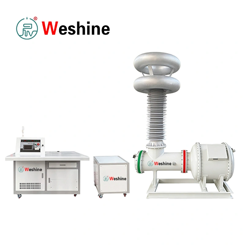
Fundamental Principles of Dielectric Withstand Testing
Dielectric withstand testing exposes electrical insulation to voltages significantly higher than normal operating levels. This stress test forces weak spots in the insulation material to break down under controlled laboratory or factory conditions. Technicians measure the resulting leakage current to determine whether the insulation barrier maintains adequate resistance. Low leakage current indicates a healthy insulation system capable of handling operational voltage spikes. High leakage current signals material degradation, moisture ingress, or inadequate physical clearance gaps between conductors.
- Apply test voltages well above normal operating thresholds to stress insulation barriers.
- Monitor microampere leakage current closely during the entire dwell time duration.
- Detect microscopic pinholes, moisture pockets, and insulation thinning before deployment.
- Prevent unexpected field failures by catching dielectric weaknesses during factory staging.
Understanding AC versus DC Testing Modalities
Choosing between alternating current and direct current testing depends on the specific capacitance characteristics of the device under test. AC testing stresses both capacitive and resistive leakage paths simultaneously within the insulation matrix. This modality replicates real-world operating stress because alternating fields continuously reverse polarity across the insulation boundary. DC testing eliminates capacitive charging current components, allowing technicians to measure purely resistive leakage current accurately. However, DC testing requires slower ramp rates to prevent sudden voltage surges that might damage sensitive electronic components.
Engineers must calculate the capacitive reactance of long power cables or large motor windings before selecting a test modality. AC systems work effectively for smaller components with low capacitance values like household appliance cords and small transformers. High-capacitance loads like underground transmission cables require DC test sets to avoid overloading test transformer capacity limits. Understanding these technical distinctions ensures accurate test results and protects valuable test assets from thermal overload.
Current Measurement and Breakdown Detection Mechanisms
Modern hipot testing instruments incorporate sophisticated current monitoring circuits to detect insulation breakdown instantly. These circuits measure leakage current in milliamperes or microamperes and compare readings against preset threshold limits. If the measured current exceeds the maximum allowable limit, the instrument cuts the high voltage output immediately. This rapid arc detection minimizes physical damage to the test specimen and protects operators from electrical hazards.
- Set precise trip current thresholds to catch marginal insulation failures instantly.
- Utilize zero-crossing turn-on circuitry to eliminate transient voltage spikes during startup.
- Discharge residual electrical energy safely through internal resistors after test completion.
- Log test results digitally to maintain complete traceability for quality assurance audits.
Comprehensive Plant Safety Protocols and Operator Protection
Operating high voltage test systems requires strict adherence to industrial safety standards to prevent personnel injuries. Technicians must establish secure testing enclosures equipped with interlock switches, warning lights, and emergency stop buttons. Safety interlocks cut power immediately if someone opens the test chamber door during an active high voltage cycle. Operators should also wear appropriate personal protective equipment and ensure proper equipment grounding before initiating any test sequence.
Facility managers must conduct regular calibration checks on all Electrical Test Equipment to maintain measurement accuracy. Calibration routines verify that output voltage levels match display readings and that trip circuits operate within specified tolerances. Documenting these maintenance procedures ensures compliance with international electrical safety codes and industry manufacturing standards.
Table 1: Comparison of Industrial Insulation Test Modalities
| Test Modality | Primary Application | Advantage | Limitation |
| AC Hipot | Transformers and Motors | Stresses dielectric in both polarities | High capacitive charging current |
| DC Hipot | Long Cables and Generators | Lower power supply requirements | Requires slow voltage ramp rates |
| Insulation Resistance | General Maintenance | Portable field diagnostic check | Lower test voltage magnitude |
Ready to upgrade your industrial testing capabilities? Contact our team today to discuss your technical specifications and project requirements.
Integrating Test Procedures into Production Workflows
Integrating electrical safety tests into assembly line workflows ensures that every manufactured unit meets required quality benchmarks. Production engineers position testing stations immediately after final mechanical assembly to catch defects early. Automated test fixtures connect directly to the test instrument, reducing operator handling time and human error risks. Passing units receive automated barcode labels confirming compliance before moving forward to final packaging.
Implementing robust Electrical Testing Equipment protocols helps manufacturers minimize warranty claims and field service costs. Documenting test data for every serial number creates a permanent quality record for regulatory compliance. Continuous data analysis allows engineering teams to identify recurring assembly flaws and adjust manufacturing parameters accordingly.
Frequently Asked Questions
What is the primary purpose of a hipot test?
A hipot test verifies the dielectric strength of electrical insulation to ensure it prevents current leakage and electrical shock.
How does AC testing differ from DC testing?
AC testing stresses insulation with alternating polarity fields, while DC testing applies a steady unidirectional voltage without capacitive charging current.
What causes a hipot tester to trip during operation?
A tester trips when leakage current exceeds the preset threshold due to insulation breakdown, excessive moisture, or physical component damage.
How often should high voltage test equipment be calibrated?
High voltage test equipment should undergo professional calibration at least once a year to ensure measurement accuracy and safety.
WESHINE delivers advanced diagnostic instrumentation and comprehensive High Voltage Testing Equipment solutions for global electrical manufacturers. Our engineering team specializes in designing reliable industrial systems that meet strict international safety and quality standards. We help businesses navigate complex technical requirements while securing dependable Electrical Testing Solutions tailored to modern grid demands.
References:
- International Electrotechnical Commission. Insulation Coordination for Equipment within Low-Voltage Systems. https://www.iec.ch
- Institute of Electrical and Electronics Engineers. IEEE Standard for Insulation Testing. https://www.ieee.org
- National Fire Protection Association. National Electrical Code Safety Guidelines. https://www.nfpa.org

