






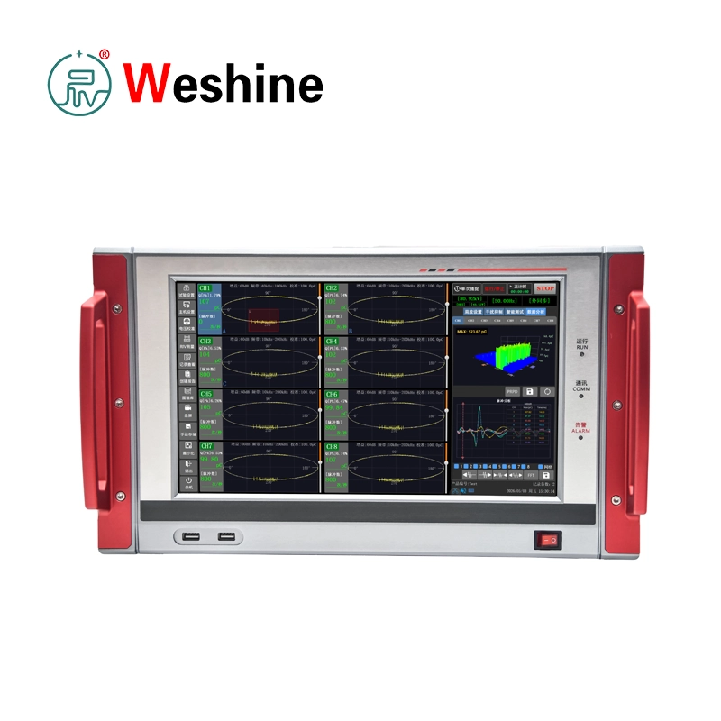


8 Channel PD Analyzer | VS-6825
Products Details
VS-6825 Eight-Channel Digital Partial Discharge Analyzer detects, records, and analyzes partial discharge in high-voltage insulation systems. Partial discharge is a localized electrical discharge within voids, cracks, interfaces, contamination areas, sharp electric field points, or aged insulation structures. Although PD does not completely bridge insulation gaps initially, repeated discharge activity gradually damages insulation and causes equipment failure if undetected.
The VS-6825 adopts an integrated industrial computer platform with eight PD measurement channels. It suits high-voltage product type testing, factory testing, commissioning tests, and field measurements. Typical test objects include motors, current transformers, voltage transformers, power cables, bushings, capacitors, power transformers, surge arresters, switchgear, and other high-voltage electrical apparatus. The system operates in laboratories and on site.
The analyzer meets IEC 60270 and GB/T 7354-2018 requirements for partial discharge measurement. It measures and records partial discharge and AC test voltage. The PD measurement range spans 0.01 pC to 10000 nC, with 12-bit sampling accuracy and an 80 MHz sampling rate per channel. Eight BNC PD input ports allow users to monitor multiple measurement points or test objects simultaneously, improving comparison efficiency during factory diagnostics.
The VS-6825 provides selectable analog filter settings. Lower frequency options include 10 kHz, 20 kHz, 40 kHz, 80 kHz, 200 kHz, and 1 MHz. Upper frequency options include 100 kHz, 200 kHz, 300 kHz, 400 kHz, 1 MHz, and 5 MHz. This flexibility lets users adapt the frequency band to specific test circuits, equipment capacitance, background noise, and site interference conditions.
The voltage measurement system supports 5 to 230 VAC RMS input, a 10 to 450 Hz frequency range, and synchronization accuracy better than 1°. The system automatically switches between power synchronization and voltage input synchronization. When voltage input exceeds 5 V, the system switches to channel voltage synchronization, aligning PD pulse information with the applied AC test voltage phase.
The analyzer uses a Core i7 quad-core 2.9 GHz industrial computer running Windows 10. A 13.3-inch true-color TFT capacitive touch screen provides 1920 × 1080 resolution for channel setup, waveform display, calibration, interference suppression, data analysis, record review, report creation, and operation management. Interfaces include 8 × BNC PD inputs, 1 × aviation voltage input, 1 × RJ45 gigabit Ethernet/LAN port, 1 × HDMI video output, 1 × RS232 interface, and 3 × standard USB ports.
The PD test circuit utilizes a coupling capacitor, test object capacitance, measuring impedance, coaxial signal cable, and analyzer input. The measuring impedance converts PD pulse current into a measurable signal and transmits it through a 50 Ω coaxial cable. Users select measuring impedance models based on test object capacitance and test circuit requirements. The manual provides twelve measuring impedance ranges covering 6 pF to 250 μF.
Before PD measurement, operators perform calibration using the supplied calibration pulse generator. The calibrator offers selectable positive and negative pulse outputs, pulse frequencies from 50 Hz to 1000 Hz, and charge quantities of 10 pC, 50 pC, 100 pC, and 500 pC. Operators remove the calibration pulse generator and connecting leads before applying high voltage.
The VS-6825 target trained high-voltage test personnel. Operators must connect the instrument to a grounded power outlet and site ground reliably. Measuring impedance ground terminals require a low-impedance connection to high-voltage system ground. Operators verify test objects are de-energized, isolated, and safe before wiring to ensure personnel safety and valid test results.
Engineers seeking robust multi-point diagnostic capability rely on this 8 Channel PD Analyzer to streamline complex quality control routines. Operating alongside high-performance partial discharge testing equipment, this platform maximizes diagnostic throughput across demanding manufacturing and field environments.
Specification
| Technical Parameters | |
| Item | Specification |
| Product model | VS-6825 |
| Product type | Eight-channel digital partial discharge analyzer |
| Main processor | Core i7, quad-core 2.9 GHz industrial computer |
| Operating system | Windows 10 |
| Display | 13.3-inch true-color TFT capacitive touch LCD |
| Display resolution | 1920 × 1080 |
| PD Measurement System | |
| Item | Specification |
| PD measurement channels | 8 channels |
| Input impedance | 50 欧姆 |
| Measurement range | 0.01 pC to 10000 nC |
| Detection sensitivity | <0.1 pC, CA = 10 nF / CK = 1 nF; <0.01 pC, CA = 1 nF / CK = 1 nF |
| Sampling accuracy | 12 bit |
| Sampling rate | 80 MHz per channel |
| Gain adjustment | 60 dB, 40 dB, 20 dB, 0 dB, -20 dB, -40 dB |
| Gain mode | Automatic or manual |
| Test object capacitance range | 6 pF to 250 μF |
| Linearity error | <±3% |
| Applicable standards | IEC 60270, GB/T 7354-2018 |
| Analog Filter | |
| Item | Specification |
| Filter type | Analog filter, -6 dB |
| Lower frequency fL | 10 kHz, 20 kHz, 40 kHz, 80 kHz, 200 kHz, 1 MHz selectable |
| Upper frequency fU | 100 kHz, 200 kHz, 300 kHz, 400 kHz, 1 MHz, 5 MHz selectable |
| Voltage Measurement System | |
| Item | Specification |
| Voltage input range | 5 to 230 VAC RMS |
| Linearity error | <±3% |
| Frequency range | 10 to 450 Hz |
| Synchronization mode | Power synchronization or voltage input synchronization automatic switching |
| Synchronization accuracy | <1° |
| Main Unit | |
| Voltage Measurement System | |
| Item | Specification |
| Voltage input range | 5 to 230 VAC RMS |
| Linearity error | <±3% |
| Frequency range | 10 to 450 Hz |
| Synchronization mode | Power synchronization or voltage input synchronization automatic switching |
| Synchronization accuracy | <1° |
| Measuring Impedance Selection | |
| Interfaces | |
| Interface | Specification |
| PD input | 8 × BNC |
| Voltage input | 1 × aviation connector |
| Gigabit Ethernet / LAN | 1 × RJ45 |
| Video output | 1 × HDMI |
| Communication interface | 1 × RS232 |
| USB | 3 × standard USB |
| Power Supply And Environment | |
| Item | Specification |
| Power supply | 176 to 264 VAC, 50/60 Hz |
| Power fuse | 250 V T 5 A |
| Operating temperature | -10°C to +50°C |
| Storage temperature | -40°C to +60°C |
| Relative humidity | 5% to 95%, non-condensing |
| Dimensions And Weight | |
| Item | Specification |
| Dimensions, W × D × H | 420 × 342 × 240 mm |
| Weight | 18.5 kg |
| Measuring Impedance Selection | |||||
| Impedance Model | Minimum Tuning Capacitance | Middle Value | Maximum Tuning Capacitance | Max RMS Current, Unbalanced Circuit | Max RMS Current, Balanced Circuit |
| 1# | 6 pF | 25 pF | 100 pF | 30 mA | 0.25 A |
| 2# | 25 pF | 100 pF | 400 pF | 60 mA | 0.5 A |
| 3# | 100 pF | 400 pF | 1500 pF | 120 mA | 1 A |
| 4# | 400 pF | 1500 pF | 6000 pF | 250 mA | 2 A |
| 5# | 1500 pF | 6000 pF | 25 nF | 500 mA | 4 A |
| 6# | 6000 pF | 25 nF | 100 nF | 1 A | 8 A |
| 7# | 25 nF | 100 nF | 400 nF | 2 A | 15 A |
| 8# | 100 nF | 400 nF | 1.5 渭F | 4 A | 30 A |
| 9# | 400 nF | 1.5 渭F | 6.0 渭F | 8 A | 60 A |
| 10# | 1.5 渭F | 6.0 渭F | 25 渭F | 15 A | 120 A |
| 11# | 6 渭F | 25 渭F | 60 渭F | 25 A | 200 A |
| 12# | 15 渭F | 60 渭F | 250 渭F | 50 A | 300 A |
| Divider Capacitor Selection | |||
| No. | Divider Capacitor C2 | Coupling Capacitor C1 | Applicable Voltage Equipment |
| 1 | 0.33 μF | Matching required | Below 66 kV |
| 2 | 1.0 μF | Matching required | 220 kV |
| 3 | 2.0 μF | Matching required | 500 kV |
| 4 | 4.0 μF | Matching required | 1000 kV |
| Calibration Pulse Generator | |
| Item | Specification |
| Dimensions | 120 × 60 × 32 mm |
| Weight | 270 g |
| Output connector | 1 × red 4 mm connector, 1 × black 4 mm connector |
| Pulse frequency | 50 Hz, 100 Hz, 200 Hz, 300 Hz, 400 Hz, 500 Hz, 600 Hz, 700 Hz, 800 Hz, 900 Hz, 1000 Hz selectable |
| Pulse type | Positive and negative pulse |
| Rise time, 10% to 90% | <30 ns |
| Pulse charge | 10 pC, 50 pC, 100 pC, 500 pC selectable |
| Standard Supply List | ||
| No. | Item | Quantity |
| 1 | Detection main unit | 1 set |
| 2 | User manual | 1 copy |
| 3 | Main unit grounding cable | 1 pc |
| 4 | 220 V power cable | 1 pc |
| 6 | 50 惟 PD signal coaxial cable | 8 pcs |
| 7 | Voltage synchronization cable | 1 pc |
| 8 | Divider-type measuring impedance | 2 pcs |
| 9 | Measuring impedance | 6 pcs |
| 10 | Coupling capacitor signal cable for measuring impedance | 8 pcs |
| 11 | Black shorting cable for measuring impedance | 8 pcs |
| 12 | Black grounding cable for impedance | 8 pcs |
| 13 | Calibration pulse generator | 1 pc |
| 14 | Black signal cable for calibration pulse generator | 1 pc |
| 15 | Red signal cable for calibration pulse generator | 1 pc |
| 16 | Charger for calibration pulse generator | 1 pc |
| 17 | USB flash drive | 1 pc |
| 18 | Factory inspection report | 1 copy |
Customer Case
-
Industry: High-voltage equipment manufacturing.
-
Problem: A manufacturer needed to perform partial discharge testing on multiple high-voltage components during factory inspection. The test team required more than four PD channels to monitor several measuring points simultaneously, reducing repeated wiring and producing consistent test records.
-
Testing Process: The team selected suitable measuring impedances according to test object capacitance. They connected coupling capacitors, measuring impedances, grounding cables, voltage synchronization input, and eight PD channels to the VS-6825. Before applying high voltage, technicians injected calibration pulses with the supplied pulse generator and completed channel calibration. After removing the calibrator, they raised test voltage and observed PD waveforms, PD magnitude, phase relationships, and synchronized voltage data on the touch screen.
-
Result: The VS-6825 provided quantitative PD readings and waveform records from multiple measurement channels. Acceptable products proceeded to final inspection, while abnormal discharge patterns were flagged for insulation review or process correction.
-
Benefits: The manufacturer reduced setup time, improved data consistency, and obtained traceable PD records for factory documentation. Eight-channel input simplified multi-point signal comparison during high-voltage tests.
Product Guide
VS-6825 measures partial discharge by acquiring high-frequency pulse signals from local insulation defects. In a typical PD test circuit, the high-voltage source energizes the test object while connected to a coupling capacitor and measuring impedance. When partial discharge occurs, pulse current passes through the measuring impedance, converting the signal into a voltage pulse. The analyzer receives the signal via 50 Ω coaxial cables and displays waveform, magnitude, and phase-related data.
Before testing, select a suitable measuring circuit and measuring impedance based on test object capacitance to keep the circuit response within amplifier bandwidth. The manual provides twelve impedance ranges covering capacitance from 6 pF to 250 μF. Common applications use 2# impedance for oil-immersed CTs/VTs, 3# for epoxy CTs/VTs, and 4# for small transformers.
Complete grounding before signal wiring. Connect the main unit to a grounded power outlet and site ground reliably. Connect the measuring impedance ground terminal to high-voltage system ground via a low-impedance path. Verify the test object is de-energized, isolated from line and load, and safe before wiring.
After circuit connection, perform PD calibration with the supplied calibration pulse generator. Select the required charge level, inject the calibration pulse into the test circuit, and complete channel calibration in the software. Remove the calibration pulse generator and leads before applying high voltage.
During testing, configure channel, gain, filter band, synchronization source, and display mode. The VS-6825 supports power synchronization or voltage input synchronization within 5 to 230 VAC RMS. Operators observe waveforms, suppress interference, analyze discharge patterns, store records, and create reports from the graphical software interface.
For field measurements, route signal cables carefully, keep grounding short and firm, select appropriate filter bands, and identify external interference sources before judging PD activity. Save test data after testing for review, diagnosis, and reporting.
Features
- Supports eight-channel digital partial discharge measurement.
- Measures PD charge from 0.01 pC to 10000 nC.
- Measures AC test voltage for synchronization and voltage monitoring.
- Provides 12-bit sampling accuracy.
- Provides 80 MHz sampling rate per channel.
- Supports 8 × BNC PD signal input.
- Supports selectable lower filter frequencies from 10 kHz to 1 MHz.
- Supports selectable upper filter frequencies from 100 kHz to 5 MHz.
- Provides detection sensitivity below 0.1 pC under CA = 10 nF and CK = 1 nF conditions.
- Provides detection sensitivity below 0.01 pC under CA = 1 nF and CK = 1 nF conditions.
- Supports automatic or manual gain adjustment from 60 dB to -40 dB.
- Supports test object capacitance range from 6 pF to 250 μF.
- Displays waveforms on a 13.3-inch true-color capacitive touch screen.
- Provides 1920 × 1080 display resolution.
- Includes Core i7 quad-core 2.9 GHz industrial computer.
- Includes Windows 10 operating system.
- Provides power synchronization and voltage input synchronization.
- Automatically switches synchronization source according to input condition.
- Includes PD calibration with a pulse generator before testing.
- Provides interference source analysis and suppression functions.
Application Scenarios
-
Power Utilities: Power utilities use the VS-6825 for PD testing of transformers, cables, switchgear, bushings, arresters, and other high-voltage assets. Eight channels allow simultaneous monitoring of multiple measurement points during commissioning or diagnostic testing.
-
Transformer Manufacturers: Transformer manufacturers use the analyzer for factory partial discharge testing of power transformers, distribution transformers, bushings, and insulation assemblies. Quantitative PD data supports quality control before shipment.
-
Power Plants: Power plants use the VS-6825 for insulation condition assessment of generator step-up transformers, motors, cables, switchgear, and station-service equipment during maintenance or acceptance testing.
-
Railways: Railway power supply systems contain high-voltage cables, transformers, switchgear, and traction power equipment. The analyzer supports insulation diagnostics during planned service windows and commissioning work.
-
Industrial Plants: Mining, petrochemical, steel, and large manufacturing plants use the VS-6825 for PD inspection of high-voltage motors, transformers, cables, and switchgear in plant power systems.
-
Universities: Universities and research institutes use the analyzer for high-voltage teaching, PD mechanism research, insulation aging studies, and waveform or phase-resolved PD analysis.
-
Testing Laboratories: High-voltage laboratories use the VS-6825 for IEC 60270 and GB/T 7354-2018 based PD measurement, product development, third-party testing, and insulation research.
-
Cable Maintenance: Cable maintenance teams use the analyzer for PD testing of power cables, joints, terminations, and accessories during commissioning, fault investigation, or periodic diagnostic work.
Applications
- Partial discharge measurement of power transformers.
- PD testing of current transformers and voltage transformers.
- Partial discharge analysis of power cables.
- Eight-channel comparative PD measurement.
- Factory testing of high-voltage electrical products.
- Type testing of insulation systems.
- Acceptance testing after installation.
- PD measurement of bushings and capacitors.
- Partial discharge inspection of surge arresters.
- PD diagnosis of high-voltage switchgear.
- Motor insulation PD testing.
- Calibration of PD test circuits before high-voltage testing.
- Interference source analysis and suppression.
- AC test voltage measurement and synchronization.
- Laboratory and field PD data recording.
FAQ
-
What partial discharge measurement range does the VS-6825 support?
The system measures PD apparent charge quantity from 0.01 pC up to 10000 nC across eight independent measurement channels.
-
Which international standards does the VS-6825 comply with?
The instrument strictly complies with IEC 60270 and GB/T 7354-2018 standards for partial discharge measurement.
-
What hardware platform powers the VS-6825 main unit?
It features an integrated industrial computer with a Core i7 quad-core 2.9 GHz processor running Windows 10 for responsive multi-channel processing.
-
How does the system synchronize with test voltage during multi-channel PD testing?
The analyzer supports power synchronization and voltage input synchronization, automatically switching to voltage synchronization when the input exceeds 5 V AC RMS.
-
Which industries commonly use the VS-6825?
Power utilities, high-voltage equipment manufacturers, testing laboratories, power plants, railways, and industrial manufacturing plants widely use it.
Weshine Advantages
Weshine Electric provides professional electrical testing equipment for power utilities, manufacturers, laboratories, contractors, and industrial users worldwide. For partial discharge testing, Weshine focuses on practical measurement circuits, stable signal acquisition, calibration support, data recording, and field usability. We supply instruments complete with accessories, factory inspection records, and technical guidance for setup and operation. Weshine assists customers with model selection, test circuit configuration, measuring impedance matching, application advice, and customized testing requirements. Delivering complete Electrical Testing Solutions, engineering experience, strict quality control, and responsive technical support, Weshine helps users perform high-voltage insulation diagnostics with clear and traceable results.