








4 Channel PD Analyzer | VS-6425
Products Details
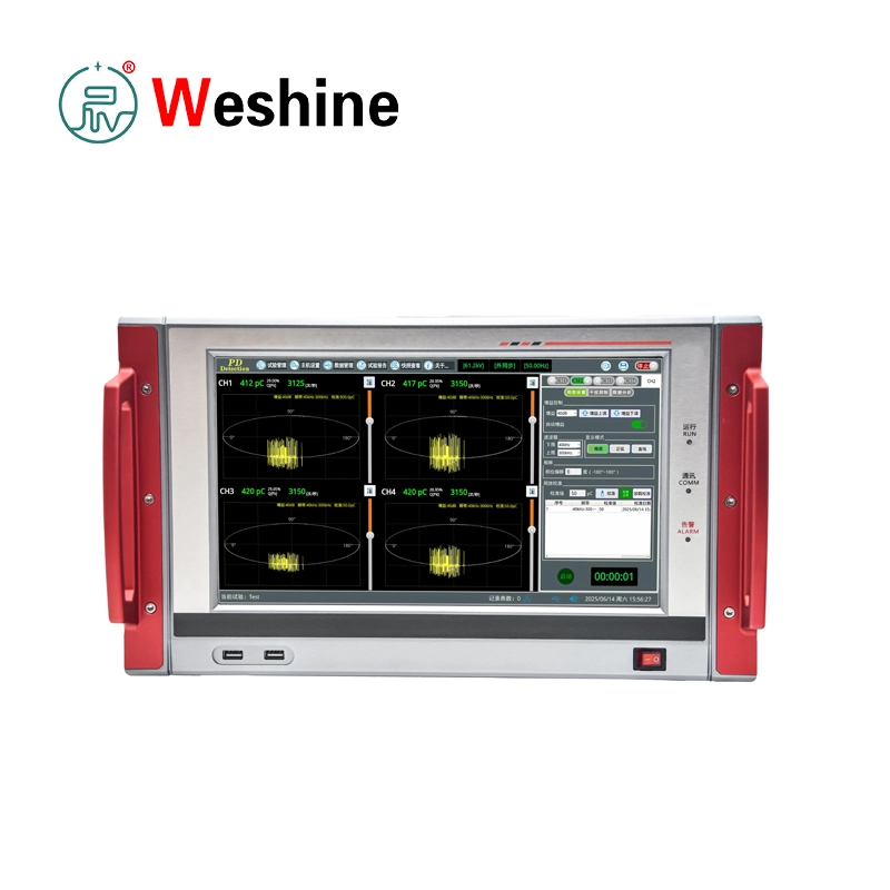
VS-6425 4 Channel PD Analyzer detects, records, and analyzes partial discharge activity in high-voltage equipment. Partial discharge represents a localized insulation breakdown. It does not fully bridge conductors, but it reveals voids, contamination, sharp field stress, aging, or manufacturing defects. Repeated PD activity accelerates insulation deterioration and increases equipment failure risks if operators do not identify it quickly.
The VS-6425 adopts an integrated digital design with four independent PD measurement channels. It suits laboratory testing and on-site measurements, including type testing, routine factory testing, commissioning tests, and diagnostic inspections. Typical test objects include motors, current transformers, voltage transformers, power cables, bushings, capacitors, transformers, surge arresters, switchgear, and other high-voltage electrical products.
The instrument complies with IEC 60270 and GB/T 7354-2018 requirements for partial discharge measurement. It measures PD charge quantity and AC test voltage, displays waveforms, supports calibration, and provides analysis and storage tools. The measuring range spans 0.01 pC to 10000 nC, with 14-bit sampling accuracy and a 100 MHz sampling rate. Selectable analog filter bandwidths help operators match specific test objects, coupling circuits, and noise environments.
The system includes PD input channels, voltage input, measuring impedance, synchronization input, a calibration pulse generator, communication interfaces, and Linux-based software. A 13.3-inch true-color capacitive touch screen provides 1920 × 1080 resolution for waveform display, channel settings, calibration, data management, and test operation. Users easily view PD waveforms, adjust parameters, perform calibration, suppress interference, and manage test records.
The PD measuring circuit consists of test object capacitance, a coupling capacitor, measuring impedance, and the analyzer input. The measuring impedance converts PD pulses into measurable electrical signals and transmits them through BNC coaxial cables. The analyzer utilizes power synchronization or voltage input synchronization. When voltage input exceeds 5 V, the system automatically switches to voltage synchronization. The voltage input range spans 5 to 230 VAC RMS with synchronization accuracy better than 1°.
Before PD measurement, operators must calibrate the test object using the supplied calibration pulse generator. This step ensures correct PD magnitude measurement. The calibrator offers selectable pulse frequencies from 50 Hz to 1000 Hz and charge quantities of 10 pC, 50 pC, 100 pC, and 500 pC. Operators remove the calibration generator and leads before applying high voltage.
Safety remains central to the VS-6425 test system. Operators must connect the analyzer to a grounded power outlet and site ground using the grounding cable. Voltage input must stay within specified AC ranges. Measuring impedance ground terminals require low-impedance connection to high-voltage system ground. Operators ensure test objects are de-energized, isolated, and safely grounded before connecting test circuits.
For engineering users, this 4 Channel PD Analyzer provides multi-channel measurement, wide filter selection, high sampling performance, calibrated charge evaluation, voltage synchronization, data storage, and analysis functions in one integrated platform. It helps manufacturers, laboratories, utilities, and maintenance teams evaluate insulation quality, compare PD patterns, document test results, and support asset condition assessment. Many power asset managers also deploy this platform alongside dedicated partial discharge testing equipment to strengthen factory quality control and field diagnostics.
Specification
PD Measurement System
| Item | Specification |
| Product model | VS-6425 |
| Product type | Four-channel digital partial discharge analyzer |
| PD measurement channels | 4 channels |
| Input impedance | 50 Ω |
| Measurement range | 0.01 pC to 10000 nC |
| Sampling accuracy | 14 bit |
| Sampling rate | 100 MHz |
| Linearity error | <±3% |
| Test object capacitance range | 6 pF to 250 μF |
| Applicable standards | IEC 60270, GB/T 7354-2018 |
Analog Filter
| Item | Specification |
| Filter type | Analog filter, -6 dB |
| Lower frequency fL | 10 kHz, 20 kHz, 40 kHz, 80 kHz, 200 kHz, 1 MHz selectable |
| Upper frequency fU | 100 kHz, 200 kHz, 300 kHz, 400 kHz, 1 MHz, 5 MHz selectable |
Detection Sensitivity
| Test Condition | Sensitivity |
| CA = 10 nF, CK = 1 nF | <0.1 pC |
| CA = 1 nF, CK = 1 nF | <0.01 pC |
Gain Adjustment
| Item | Specification |
| Gain levels | 60 dB, 40 dB, 20 dB, 0 dB, -20 dB, -40 dB |
| Adjustment mode | Automatic or manual |
Voltage Measurement System
| Item | Specification |
| Voltage input range | 5 to 230 VAC RMS |
| Linearity error | <±3% |
| Frequency range | 10 to 450 Hz |
| Synchronization mode | Power synchronization or voltage input synchronization automatic switching |
| Synchronization accuracy | <1° |
Interfaces
| Interface | Specification |
| PD input | 4 × BNC |
| Voltage input | 1 × aviation connector |
| Communication interface | 1 × RJ45, 1 × RS232 |
| USB | Front-panel USB interface |
Main Unit
| Item | Specification |
| Operating system | Linux |
| Storage | 8 GB or above |
| Display | 13.3-inch true-color TFT capacitive touch LCD |
| Resolution | 1920 × 1080 |
| Power supply | 176 to 264 VAC, 50/60 Hz |
| Power fuse | 250 V T 5 A |
| Operating temperature | -10°C to +50°C |
| Storage temperature | -40°C to +60°C |
| Relative humidity | 5% to 95%, non-condensing |
| Dimensions | 445 × 458 × 236 mm |
| Weight | 11.7 kg |
Measuring Impedance Selection
| Impedance Model | Minimum Tuning Capacitance | Middle Value | Maximum Tuning Capacitance | Max RMS Current, Unbalanced Circuit | Max RMS Current, Balanced Circuit |
| 1# | 6 pF | 25 pF | 100 pF | 30 mA | 0.25 A |
| 2# | 25 pF | 100 pF | 400 pF | 60 mA | 0.5 A |
| 3# | 100 pF | 400 pF | 1500 pF | 120 mA | 1 A |
| 4# | 400 pF | 1500 pF | 6000 pF | 250 mA | 2 A |
| 5# | 1500 pF | 6000 pF | 25 nF | 500 mA | 4 A |
| 6# | 6000 pF | 25 nF | 100 nF | 1 A | 8 A |
| 7# | 25 nF | 100 nF | 400 nF | 2 A | 15 A |
| 8# | 100 nF | 400 nF | 1.5 μF | 4 A | 30 A |
| 9# | 400 nF | 1.5 μF | 6.0 μF | 8 A | 60 A |
| 10# | 1.5 μF | 6.0 μF | 25 μF | 15 A | 120 A |
| 11# | 6 μF | 25 μF | 60 μF | 25 A | 200 A |
| 12# | 15 μF | 60 μF | 250 μF | 50 A | 300 A |
Divider Capacitor Selection
| No. | Divider Capacitor C2 | Coupling Capacitor C1 | Applicable Voltage Equipment |
| 1 | 0.33 μF | Matching required | Below 66 kV |
| 2 | 1.0 μF | Matching required | 220 kV |
| 3 | 2.0 μF | Matching required | 500 kV |
| 4 | 4.0 μF | Matching required | 1000 kV |
Calibration Pulse Generator
| Item | Specification |
| Dimensions | 120 × 60 × 32 mm |
| Weight | 270 g |
| Output connectors | 1 × red 4 mm connector, 1 × black 4 mm connector |
| Pulse frequency | 50 Hz, 100 Hz, 200 Hz, 300 Hz, 400 Hz, 500 Hz, 600 Hz, 700 Hz, 800 Hz, 900 Hz, 1000 Hz selectable |
| Pulse type | Positive and negative pulse |
| Rise time, 10% to 90% | <30 ns |
| Pulse charge | 10 pC, 50 pC, 100 pC, 500 pC selectable |
Standard Supply List
| No. | Item | Quantity |
| 1 | Detection main unit | 1 set |
| 2 | User manual | 1 copy |
| 3 | Main unit grounding cable | 1 pc |
| 4 | 220 V power cable | 1 pc |
| 6 | 50 Ω PD signal coaxial cable | 4 pcs |
| 7 | Voltage synchronization cable | 1 pc |
| 8 | Divider-type measuring impedance | 1 pc |
| 9 | Measuring impedance | 3 pcs |
| 10 | Coupling capacitor signal cable for measuring impedance | 4 pcs |
| 11 | Black shorting cable for measuring impedance | 4 pcs |
| 12 | Black grounding cable for impedance | 4 pcs |
| 13 | Calibration pulse generator | 1 pc |
| 14 | Black signal cable for calibration pulse generator | 1 pc |
| 15 | Red signal cable for calibration pulse generator | 1 pc |
| 16 | Charger for calibration pulse generator | 1 pc |
| 17 | USB flash drive | 1 pc |
| 18 | Factory inspection report | 1 copy |
Customer Case
-
Industry: High-voltage equipment manufacturing.
-
Problem: A manufacturer needed to perform partial discharge tests on high-voltage instrument transformers before shipment. The test team required multi-channel PD measurement, calibrated charge values, voltage synchronization, and reliable waveform recording to support factory quality control.
-
Testing Process: The team selected measuring impedance according to test object capacitance. They connected the coupling capacitor, measuring impedance, voltage input, grounding cable, and four PD input channels. Before applying high voltage, technicians injected calibration pulses with the calibration pulse generator to calibrate channels. After removing the calibrator, they applied test voltage and monitored PD waveforms, PD magnitude, phase relation, and voltage synchronization from the VS-6425 touch screen.
-
Result: The analyzer provided quantitative PD readings and stored waveform records for each unit. Products with acceptable PD behavior continued to final inspection, while units showing abnormal discharge patterns were held for insulation review.
-
Benefits: The manufacturer improved test traceability, reduced manual comparison work, and obtained consistent PD records for factory documentation. Four-channel input allowed the team to evaluate multiple signal points simultaneously.
Product Guide
VS-6425 measures partial discharge by connecting the test object, coupling capacitor, measuring impedance, voltage synchronization input, and analyzer into a PD test circuit. When partial discharge occurs inside or on insulation surfaces, the discharge generates high-frequency pulse current. The measuring impedance converts this pulse into a voltage signal, transmitting it to the analyzer through a 50 Ω coaxial cable to display PD waveforms and phase-related data.
Before measurement, select the proper test circuit according to the test object. The system supports capacitive and inductive test objects. Technicians select measuring impedance based on test object capacitance and coupling capacitance to ensure operation within effective tuning ranges. Twelve impedance models cover capacitances from 6 pF to 250 μF.
Technicians complete grounding before wiring. Connect the analyzer to a grounded power supply and site ground using the grounding cable. The measuring impedance ground terminal requires a low-impedance connection to high-voltage system ground. Confirm the test object is fully de-energized, isolated, and safe before connecting the instrument.
After circuit connection, perform PD calibration with the calibration pulse generator. Calibration before high-voltage testing ensures correct apparent charge measurement. Select the appropriate pulse charge value, inject the calibration signal into the test circuit, and complete channel calibration in the software. Remove the calibration pulse generator and leads before applying high voltage.
Configure channel parameters, filter bandwidth, gain, synchronization source, and display mode. Operators use the touch screen interface to configure PD settings, interference suppression, intelligent test functions, and data analysis tools. Raise high voltage according to applicable test procedures while monitoring PD waveforms, PD magnitude, phase position, and test voltage.
For field testing, analyze interference sources before judging PD activity. Apply proper grounding, cable routing, filter selection, and interference suppression functions to reduce noise influence. Save test records after measurement, including waveform data and test details, for later review and report generation.
Features
- Supports four-channel digital partial discharge measurement.
- Measures PD charge from 0.01 pC to 10000 nC.
- Measures AC test voltage through voltage input synchronization.
- Provides 14-bit sampling accuracy.
- Provides 100 MHz sampling rate.
- Supports selectable analog lower filter frequencies from 10 kHz to 1 MHz.
- Supports selectable analog upper filter frequencies from 100 kHz to 5 MHz.
- Provides detection sensitivity below 0.1 pC under CA = 10 nF and CK = 1 nF conditions.
- Provides detection sensitivity below 0.01 pC under CA = 1 nF and CK = 1 nF conditions.
- Supports automatic or manual gain adjustment from 60 dB to -40 dB.
- Supports test object capacitance range from 6 pF to 250 μF.
- Displays PD waveforms on a 13.3-inch true-color capacitive touch screen.
- Includes 1920 × 1080 display resolution.
- Provides power synchronization and voltage input synchronization.
- Automatically switches synchronization mode according to voltage input condition.
- Supports PD calibration before high-voltage testing.
- Includes interference analysis and suppression functions.
- Provides data processing, test storage, and record management.
- Includes RJ45 and RS232 communication interfaces.
- Supports laboratory and field PD testing of multiple high-voltage equipment types.
Application Scenarios
-
Power Utilities: Power utilities use the VS-6425 for condition assessment of transformers, cables, GIS-related components, bushings, arresters, and switchgear. Four-channel measurement compares signals from multiple points to support maintenance and commissioning decisions.
-
Transformer Manufacturers: Transformer manufacturers use the analyzer for factory PD testing of power transformers, distribution transformers, bushings, and insulation assemblies. Quantitative PD data supports quality control before delivery.
-
Power Plants: Power plants use the VS-6425 for acceptance and maintenance testing of generator step-up transformers, motors, switchgear, cables, and station-service electrical equipment.
-
Railways: Railway power supply systems deploy high-voltage cables, transformers, switchgear, and traction power equipment. The VS-6425 supports insulation diagnostics during maintenance windows and commissioning tests.
-
Industrial Plants: Facilities such as mining, petrochemical, steel, and manufacturing plants use the analyzer for high-voltage motor, transformer, cable, and switchgear PD inspection.
-
Universities: Universities and research institutes use the VS-6425 for teaching and research regarding partial discharge mechanisms, insulation aging, PD pattern analysis, and high-voltage testing methods.
-
Testing Laboratories: High-voltage laboratories use the analyzer for IEC 60270 and GB/T 7354-2018 based PD testing, equipment development, insulation research, and third-party test services.
-
Cable Maintenance: Cable maintenance teams use the VS-6425 for PD testing of power cables, cable accessories, joints, and terminations during commissioning or diagnostic inspection.
Applications
- Partial discharge measurement of power transformers.
- PD testing of current transformers and voltage transformers.
- Partial discharge analysis of power cables.
- Factory PD testing of high-voltage electrical products.
- Type testing of insulation systems.
- Acceptance testing after equipment installation.
- PD testing of bushings and capacitors.
- Partial discharge inspection of surge arresters.
- PD diagnosis of high-voltage switchgear.
- Motor insulation PD testing.
- Four-channel comparative PD measurement.
- PD calibration before high-voltage testing.
- Interference source analysis and suppression.
- AC test voltage measurement and synchronization.
- Laboratory and field PD data recording.
FAQ
-
What partial discharge measurement range does the VS-6425 support?
The system measures PD apparent charge quantity from 0.01 pC up to 10000 nC across four independent measurement channels.
-
Which international standards does the VS-6425 comply with?
The instrument strictly complies with IEC 60270 and GB/T 7354-2018 standards for partial discharge measurement.
-
What test objects can be evaluated using the VS-6425?
It evaluates power transformers, instrument transformers, power cables, switchgear, motors, bushings, capacitors, surge arresters, and other high-voltage electrical assets.
-
How does the system synchronize with test voltage during PD testing?
The analyzer supports power synchronization and voltage input synchronization, automatically switching to voltage synchronization when the input exceeds 5 V AC RMS.
-
Which industries commonly use the VS-6425?
Power utilities, high-voltage equipment manufacturers, testing laboratories, power plants, railways, and industrial manufacturing plants widely use it.
Weshine Advantages
Weshine Electric provides professional electrical testing equipment for power utilities, manufacturers, laboratories, contractors, and industrial users worldwide. For partial discharge testing, Weshine focuses on practical measurement circuits, stable signal acquisition, calibration support, data recording, and field usability. We supply instruments complete with accessories, factory inspection records, and technical guidance for setup and operation. Weshine assists customers with model selection, test circuit configuration, measurement impedance matching, application advice, and customized testing requirements. Delivering comprehensive Electrical Testing Solutions, engineering experience, strict quality control, and responsive technical support, Weshine helps users perform high-voltage insulation diagnostics with clear and traceable results.