






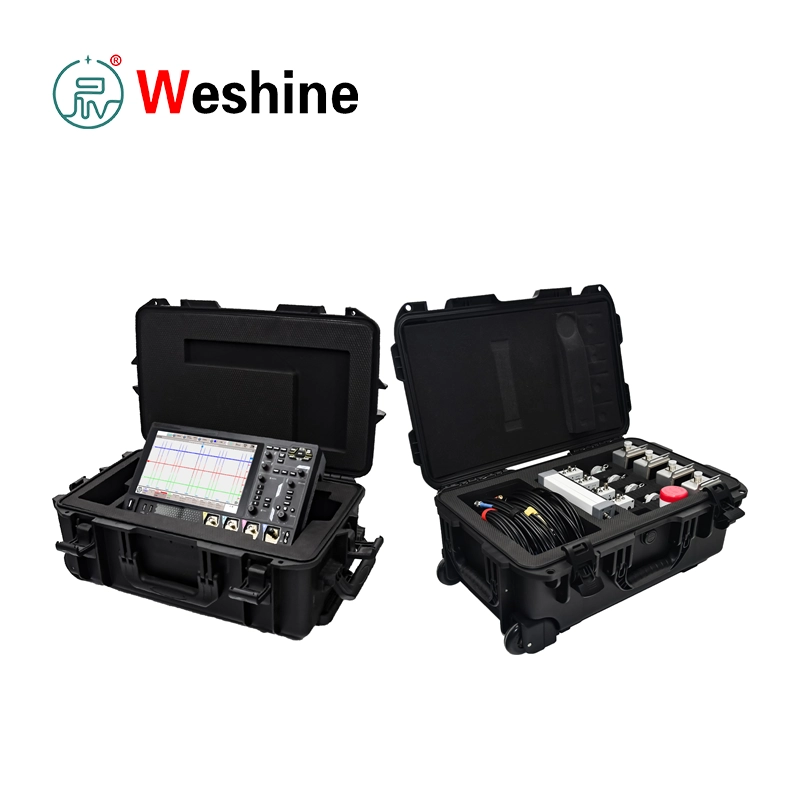


Partial Discharge Online Monitoring System | VS-L700
Products Details
VS-L700 Partial Discharge Detection and Locating System is purpose-built for live detection and spatial locating of localized insulation breakdowns in high-voltage assets. Partial discharge (PD) represents a localized pulse discharge phenomenon that frequently initiates when electrical insulation suffers from internal defects, surface contamination, structural voids, floating conductive particles, loose contact interfaces, or excessive localized electric field stress. Across critical high-voltage infrastructure—such as GIS assemblies, power transformers, shunt reactors, power cables, and metal-clad switchgear—active PD phenomena continuously emit ultra-high-frequency electromagnetic waves, high-frequency pulse currents, acoustic ultrasonic emissions, transient light, localized heat, and gaseous chemical byproducts. Extracting and capturing these physical signals serves as a vital diagnostic foundation for accurate, non-invasive insulation condition assessments.
Designed for comprehensive diagnostic coverage, the VS-L700 integrates multiple advanced sensing modalities into a cohesive, portable field system. It leverages Ultra-High Frequency (UHF) detection, High-Frequency Current Transformer (HFCT) sensing, Radio Frequency (RF) coupling, and Ultrasonic (AE) measurement. By performing comparative cross-analysis between electromagnetic radiation and acoustic wave emissions, this partial discharge online monitoring system enables engineers to effectively differentiate genuine internal insulation discharges from pervasive ambient field interference. This multi-modal acoustic-electrical fusion strategy substantially increases the confidence of PD source localization and defect severity classification.
For gas-insulated switchgear (GIS) diagnostics, the UHF technique serves as the core evaluation mechanism. Upon the inception of internal PD within a GIS enclosure, the extremely rapid breakdown process generates steep current pulses featuring sub-nanosecond rise times (under 1 ns), subsequently radiating electromagnetic waves spanning from hundreds of megahertz up to the gigahertz spectrum. Utilizing specialized UHF sensors, the VS-L700 captures these radiated signals through non-metallic aperture points, such as insulating spacers, grounding switch insulators, cable terminations, and inspection windows. Given that typical air-borne corona noise and industrial radio interference are predominantly concentrated below 300 MHz, high-frequency UHF sensing inherently suppresses low-frequency ambient interference.
To evaluate ground paths across power cables, transformers, reactors, GIS compartments, and switchgear cabinets, the HFCT detection channel acquires transient high-frequency current pulses coupled directly into grounding conductors. The specialized HFCT clamp-on sensor attaches securely around earth leads or dedicated grounding buses, successfully intercepting micro-ampere pulse currents whenever localized discharge energy couples through internal distributed capacitance into the earthing system.
For specialized medium-voltage and high-voltage cable joint inspections where dedicated earth leads or accessible grounding straps are unavailable, the VS-L700 accommodates high-sensitivity RF coupling sensors. These sensors clip or attach directly onto the insulated cable body, offering an adaptable, non-invasive diagnostic alternative for complex cable networks where traditional clamp-on HFCT deployment is constrained.
To execute pinpoint acoustic-electrical localization, the system integrates precision contact ultrasonic detection. High-voltage electrical discharges induce mechanical micro-vibrations, propagating acoustic energy across a broad frequency band. The included high-gain ultrasonic preamplifier working alongside differential ultrasonic sensors captures subtle mechanical acoustic waves travelling through transformer oil tanks and GIS metallic enclosures. By calculating the precise arrival time delay between the instantaneous UHF electromagnetic trigger and the subsequent mechanical acoustic wave, maintenance technicians can compute the spatial distance to the defect origin. Under practical field conditions, standalone UHF time-difference mapping isolates the emission source within approximately 1 meter, whereas combined acoustic-electrical multi-point correlation further refines location precision down to exact physical compartments.
At the core of the system is an integrated, high-performance digital storage oscilloscope boasting a 10 GSa/s real-time sampling rate, 1 GHz analog bandwidth, 500 Mpts deep memory, 4 synchronous detection channels, and an intuitive 10.1-inch multi-touch capacitive display. This hardware platform enables field engineers to meticulously analyze high-frequency pulse detail, phase-resolved periodic characteristics, fast pulse-trigger timing, and nanosecond delay relationships across UHF, HFCT, RF, and acoustic channels. Comprehensive high-resolution waveform screenshots and raw binary time-series data can be archived internally for post-test signal processing and professional diagnostic reporting.
Engineered specifically for certified high-voltage field technicians, the VS-L700 operates strictly under established substation safety protocols. The technical documentation emphasizes that the analyzer main unit and its auxiliary sensors must never be attached directly to energized high-voltage primary conductors. Prior to conducting on-site measurements, operators should systematically verify cable integrity, earth bonding, sensor connections, and battery levels. Establishing a baseline environmental background noise baseline prior to active PD evaluation, selecting optimal hardware frequency filters, and thoroughly documenting spatial measurement points alongside site photos ensure reliable, repeatable field diagnostics. To support comprehensive diagnostic routines, Weshine Electric operates as a trusted Electrical Testing Equipment Supplier, delivering comprehensive field instrumentation and technical support across high-voltage asset management programs.
Technical Parameters
| Sampling Host | |
| Item | Specification |
| Product model | VS-L700 |
| Product type | Partial discharge detection and locating system |
| System sampling rate | 10 GSa/s |
| System analog bandwidth | 1 GHz |
| Memory depth | 500 Mpts |
| Detection channels | 4 |
| Screen | 10.1-inch multi-touch capacitive screen |
| Power supply | Lithium battery power supply |
| UHF Partial Discharge Signal Conditioner | HFCT Partial Discharge Signal Conditioner | ||
| Item | Specification | Item | Specification |
| Item | Specification | HFCT channels | 4 channels |
| UHF channels | 4 channels | Filter | BW1, BW2, BW3 adjustable |
| Filter | High-pass, low-pass, band-pass selectable | Filter purpose | Select higher signal-to-noise frequency band according to site interference |
| Detection function | Pre-detection and post-detection adjustable output for pulse analysis | Gain | Low gain and high gain selectable |
| Gain | Low gain and high gain selectable | Detection function | Pre-detection and post-detection adjustable output for pulse analysis |
| Power supply | 7.4 V lithium battery | Power supply | 7.4 V lithium battery |
| Battery life | 5 days | Battery life | 5 days |
| Interface | BNC output, BNC output | Interface | BNC output, BNC output |
| Ultrasonic Preamplifier | |
| Item | Specification |
| Bandwidth | 20 kHz to 1200 kHz |
| Gain | 20 dB, 40 dB, 60 dB adjustable |
| Input mode | Single-ended and differential adjustable |
| Power supply | 7.4 V lithium battery |
| Battery life | 8 hours |
| UHF Sensor | HFCT Sensor | ||
| Item | Specification | Item | Specification |
| Detection bandwidth | 300 MHz to 1500 MHz | Detection bandwidth | 500 kHz to 30 MHz |
| Equivalent height | >8 | Transfer impedance | >10 |
| Contact Ultrasonic Sensor | |
| Item | Specification |
| Sensor type | Differential type |
| Detection bandwidth | 20 kHz to 300 kHz |
| RF Coupling Sensor | |
| Item | Specification |
| Detection bandwidth | 3 kHz to 30 MHz |
| Test method | Attached to cable body |
| Application note | Used for cable joint sites without grounding lead access |
| Operating Environment | |
| Item | Specification |
| Operating temperature | 0°C to +50°C |
| Non-operating temperature | -30°C to +70°C |
| Operating humidity, below +30°C | ≤90% RH, non-condensing |
| Operating humidity, +30°C to +40°C | ≤75% RH, non-condensing |
| Operating humidity, +40°C to +50°C | ≤45% RH, non-condensing |
| Non-operating humidity, below +65°C | ≤90% RH, non-condensing |
| Oscilloscope Functions From Manual | |
| Item | Specification / Function |
| Analog bandwidth | 1 GHz |
| Maximum sampling rate | 10 GSa/s |
| Single-channel single acquisition storage | 500 M sampling points |
| Channel impedance for UHF, AE, HFCT tests | 50 Ω |
| Recommended periodic observation time base | 20 ms/div or 10 ms/div |
| Recommended location analysis time base | 20 ns/div or 50 ns/div |
| Image storage formats | PNG, BMP, JPG |
| Waveform storage formats | BIN, CSV, WFM |
Customer Case
-
Industry: Power utility substation maintenance.
-
Problem: During routine maintenance within an energized utility substation, field inspectors registered anomalous discharge indications along a primary GIS bay. Because the surrounding grid topology prevented an immediate forced outage, maintenance personnel required a reliable live diagnostic solution to verify whether the recorded signals reflected genuine internal GIS insulation deterioration or harmless ambient background noise, while accurately pinpointing the suspect defect zone.
-
Testing Process: Substation engineers deployed the VS-L700 system configured with high-sensitivity UHF sensors to first establish local background noise baselines across non-metallic GIS apertures. By adjusting hardware bandpass filters on the UHF signal conditioner, the team analyzed phase-resolved periodic discharge trends via the post-detection output path. Once consistent localized PD signatures were identified, technicians shifted to the pre-detection output mode, using oscilloscope pulse triggering to calculate exact signal arrival time differences. Subsequently, differential contact ultrasonic sensors were mounted along the suspect enclosure section, using the primary UHF signal as a precise zero-time reference for acoustic-electrical distance tri-angulation.
-
Result: The diagnostic team successfully isolated the active partial discharge source to a specific internal GIS compartment. They systematically recorded high-resolution pulse waveforms, time-delay calculations, exact measurement coordinates, and high-definition site photos. This definitive diagnostic dataset provided asset managers with verifiable engineering data to justify and schedule a targeted maintenance outage.
-
Benefits: By utilizing this multi-sensor workflow, the power utility successfully avoided costly unguided disassembly, confidently separated true internal insulation discharges from heavy outdoor electromagnetic interference, and generated traceable evidence to optimize maintenance decision-making. The combined application of UHF, HFCT, RF, and ultrasonic diagnostics provided total confidence in the physical location of the defect.
Product Guide & Testing Workflow
The VS-L700 operates on the principle of multi-physical phenomenon acquisition: capturing distinct physical emissions originating from a single localized discharge event. Electromagnetic wave emissions are detected by high-frequency UHF sensors, transient pulse currents flowing in ground circuits are picked up by HFCT transducers, cable sheath signals are acquired via direct-contact RF coupling sensors, and localized structural vibrations are recorded by sensitive ultrasonic sensors. Cross-evaluating these complementary channels enables the operator to determine whether active PD exists and pinpoint its exact structural origin.
-
Pre-Test Preparation: Prior to entering the substation field site, confirm that the internal battery charge level of all system modules is above 50%. If the power level drops below 50%, fully recharge the modules prior to deployment. The dedicated battery charger displays a solid red indicator during active charging and switches to green once full capacity is reached. For optimal measurement stability and operator safety, do not operate the test equipment while connected to AC line chargers.
-
GIS Initial Assessment & Noise Baselines: For GIS asset evaluations, initiate testing using the UHF channels. Always take ambient background noise measurements prior to attaching sensors to primary asset enclosures. If heavy environmental electromagnetic interference is present, select appropriate filtering modes—such as high-pass, low-pass, or tailored band-pass configurations—on the UHF signal conditioning unit. Operators can utilize the post-detection output mode to monitor long-term phase-resolved periodic patterns, then transition to pre-detection mode for transient pulse shape examination and time-difference triangulation.
-
Sensor Placement & Signal Verification: Position UHF sensors against non-metallic aperture points where internal electromagnetic waves naturally leak out from the metallic shield, such as epoxy insulating spacers, grounding switch insulators, cable sealing ends, observation ports, or unshielded joint windows. If no active signals are detected, systematically progress across remaining inspection points. When a suspect signal is identified, perform position-based amplitude comparisons and nanosecond time-difference correlation to confirm whether the signal originates internally or radiates from external site interference.
-
Time-Difference Spatial Location: To pinpoint the discharge origin along a linear asset, implement UHF time-difference diagnostic routines. Set the oscilloscope time base to a fast sweep speed, such as 20 ns/div or 50 ns/div, and enable stable pulse trigger mode. Designate one sensor channel as the fixed reference trigger, then compare the microsecond/nanosecond arrival time differences from adjacent sensor positions to calculate physical distance offsets.
-
Acoustic-Electrical Fine Pinpointing: Once UHF analysis narrows the defect to a local compartment, apply combined acoustic-electrical confirmation. Mount the contact ultrasonic sensor against the outer enclosure wall near the suspect area, utilizing the instantaneous UHF electromagnetic pulse as the zero-time trigger reference. By measuring the precise arrival delay of the slower ultrasonic acoustic wave and factoring in the acoustic propagation velocity through the specific medium (oil or $\text{SF}_6$ gas), operators can fine-tune the spatial location of the defect.
-
Phase Identification & Cable Sheath Testing: On three-phase common-enclosure GIS or power cable banks, deploy HFCT sensors around adjacent phase grounding conductors or metallic sheath leads to isolate the specific faulted phase. The phase exhibiting severe internal discharge typically displays higher peak pulse current amplitudes and distinct phase-angle alignment compared to healthy adjacent phases. For advanced diagnostics across complex cable architectures, integrating a dedicated Partial Discharge Test System alongside RF body-coupling techniques ensures complete diagnostic coverage.
-
Documentation & Report Generation: Upon completing signal localization, capture and store high-resolution waveform traces alongside raw data files directly within the oscilloscope memory. Record the exact sensor coordinates, physical equipment numbers, filter settings, and high-resolution site photographs to build a traceable diagnostic file for maintenance scheduling.
Features
- Supports live partial discharge detection on GIS, transformers, reactors, switchgear, and power cables.
- Supports UHF, HFCT, RF coupling, and ultrasonic detection methods.
- Provides four UHF signal conditioning channels for GIS field testing.
- Provides four HFCT signal conditioning channels for grounding current PD detection.
- Includes four low-noise ultrasonic preamplifier channels.
- Includes differential ultrasonic sensors for GIS and transformer testing.
- Supports RF coupling sensor testing for cable joints without grounding leads.
- Provides UHF high-pass, low-pass, and band-pass filter selection.
- Provides HFCT BW1, BW2, and BW3 band-pass filter selection.
- Supports high and low gain selection for UHF and HFCT signal conditioning.
- Provides pre-detection and post-detection output modes for pulse analysis and periodic pattern observation.
- Displays waveform details through a high-speed digital storage oscilloscope.
- Provides 10 GSa/s system sampling rate.
- Provides 1 GHz analog bandwidth.
- Provides 500 Mpts memory depth.
- Supports pulse trigger capture for time-difference location.
- Detects phase-related and waveform-related PD characteristics.
- Calculates PD source location using acoustic-electrical combined analysis.
- Supports waveform image and waveform data storage.
- Provides battery-powered field operation for signal conditioners and preamplifiers.
Application Scenarios
- Power Utilities
Power utilities use the VS-L700 for live PD inspection of GIS, transformers, reactors, switchgear, and cables in substations. The system helps maintenance teams identify insulation defects without immediate equipment shutdown. - Transformer Manufacturers
Transformer manufacturers can use the ultrasonic and HFCT functions for discharge signal investigation during factory diagnosis, troubleshooting, and quality inspection of transformer insulation systems. - Power Plants
Power plants use the system for condition inspection of transformers, reactors, switchgear, and high-voltage cable systems in switchyards and auxiliary power networks. - Railways
Railway traction substations use GIS, cables, transformers, and switchgear in compact installations. The VS-L700 supports live PD detection during scheduled inspection windows. - Industrial Plants
Large industrial facilities such as mining, petrochemical, steel, and manufacturing plants can use the system for live inspection of high-voltage switchgear, transformers, reactors, and cable joints. - Universities
Universities and research institutes can use the VS-L700 for PD detection training, UHF signal analysis, ultrasonic location research, and acoustic-electrical combined diagnostic studies. - Testing Laboratories
Electrical testing laboratories can use the system for on-site PD investigation, insulation defect location, waveform analysis, and third-party diagnostic service. - Cable Maintenance
Cable maintenance teams can use HFCT and RF coupling sensors to detect PD in cables, cable joints, and terminations, especially where grounding lead access is limited.
Applications
- Live PD detection of GIS equipment.
- UHF partial discharge inspection in substations.
- HFCT pulse current detection on grounding conductors.
- Ultrasonic PD location on GIS and transformers.
- RF coupling detection on power cable bodies.
- PD source location using time-difference analysis.
- Acoustic-electrical combined PD locating.
- Cable joint PD inspection without grounding lead access.
- Transformer partial discharge field investigation.
- Reactor partial discharge detection.
- Switchgear live PD inspection.
- Three-phase GIS defective phase identification.
- Background noise measurement before PD testing.
- Waveform image and waveform data storage.
- Field record preparation for maintenance analysis.
FAQ
-
What is the VS-L700 used for? The VS-L700 is used for live partial discharge detection and location in GIS, transformers, reactors, switchgear, and power cables. It combines UHF, HFCT, RF coupling, and ultrasonic detection methods.
-
What is the working principle of the VS-L700? The system collects electromagnetic, pulse current, RF coupling, and ultrasonic signals produced by partial discharge. By comparing waveform features, periodic characteristics, and signal arrival time differences, the operator can detect and locate the PD source.
-
Why does the system use both electrical and ultrasonic methods? Electrical methods such as UHF and HFCT provide high sensitivity and fast pulse timing. Ultrasonic detection helps confirm the physical location of the discharge source. Combining both methods improves interference rejection and location accuracy.
-
What equipment can be tested with the VS-L700? The system can be used on GIS, transformers, reactors, switchgear, power cables, cable joints, and other medium-voltage or high-voltage electrical equipment.
-
What is the UHF sensor frequency range? The UHF sensor detection bandwidth is 300 MHz to 1500 MHz.
-
What is the HFCT sensor frequency range? The HFCT sensor detection bandwidth is 500 kHz to 30 MHz.
-
Can the VS-L700 test cable joints without grounding leads? Yes. The RF coupling sensor can be attached to the cable body and is intended for cable joint sites where no grounding lead is available.
-
What safety precautions are required? The system and sensors must not be directly connected to high-voltage terminals. Operators should follow substation safety rules, use suitable sensors and accessories, check cables and grounding, avoid working alone, and operate only after proper safety training.
Weshine Advantages
Weshine Electric provides electrical testing equipment for power utilities, substations, laboratories, contractors, and industrial users. For partial discharge detection and location, Weshine focuses on practical field methods, multi-sensor diagnosis, waveform analysis, and reliable testing support. Weshine can assist customers with sensor selection, test workflow, interference judgment, and application guidance for GIS, transformers, switchgear, and cable systems. With engineering experience, quality control, technical support, customized solutions, reliable testing products, and international service, Weshine helps users improve insulation condition assessment and maintenance planning for high-voltage assets.