






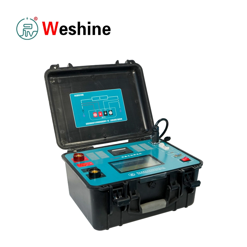


Dual-ClampContact Resistance Tester | VS-5203+
Product Details
Weshine Electric develops the VS-5203+ Non-disassembly Contact Resistance Tester based on DL/T 845.4-2019 and IEC-standard four-wire resistance measurement principles for high-current electrical testing applications. Operating as an essential innovation within our flagship contact resistance tester category, this instrument eliminates the need to dismantle grounding connections during field inspection.
The instrument integrates a high-power constant current injection system with a multi-channel current sensing architecture. This design ensures stable current output and accurate voltage sampling even in complex parallel grounding networks.
Core Measurement Architecture
The VS-5203+ combines two key technologies:
-
High-current constant injection (50A–300A)
-
Wireless clamp current detection (DC 0 to ±600A)
The system calculates true circuit resistance using Ohm’s Law:
R = V / I₀
Where V is the measured voltage drop across the contact point, and I₀ is the actual current flowing through the tested branch.
Intelligent Testing Modes (Core Innovation)
Weshine Electric integrates four advanced testing modes to support different field conditions:
-
Traditional Circuit Resistance Mode
This mode applies standard four-wire Kelvin measurement. Operators disconnect one side of the grounding system to eliminate shunt current influence. The system injects high DC current (up to 300A) into the circuit and measures voltage drop across the contact point. This mode ensures maximum measurement accuracy in controlled maintenance environments.
-
Clamp Direct Measurement Mode
This mode enables non-disassembly testing. A wireless clamp sensor measures real-time total current (I₀) flowing through the tested circuit. The system eliminates the need for grounding disconnection and calculates resistance using:
R = V / I₀
-
Key Advantages: No grounding removal required, higher field efficiency, and improved safety in live maintenance environments.
-
-
Single-Side Shunt Mode
This mode applies to parallel grounding systems such as enclosure grounding or distributed grounding networks. A clamp sensor measures branch shunt current (I₂). The system calculates true circuit current using I₀ = I₁ − I₂, and then determines resistance using:
R = V / (I₁ − I₂)
This mode improves accuracy in partial parallel current systems.
-
Dual-Side Shunt Mode
This mode applies to complex grounding networks with bidirectional current splitting. Two clamp sensors measure branch currents (I₂₁ and I₂₂). The system calculates I₀ = I₁ − I₂₁ − I₂₂, and determines resistance using:
R = V / I₀
This mode ensures accurate measurement in large substations and multi-branch grounding grids.
Safety and Clamp System Design
Weshine Electric integrates wireless clamp sensors with DC current direction recognition technology.
-
Key Clamp Specifications:
-
DC measurement range: 0 to ±600A
-
Direction-sensitive installation (forward current orientation required)
-
Calibration support in system settings
-
-
Safety Rules for Stable Operation:
-
Clamp overload beyond range may damage sensor
-
Correct directional installation improves accuracy
-
Calibration function compensates for deviation
-
Technical Specifications
| Parameter | Specification |
| Product Model | VS-5203+ |
| Test Current | 50A / 100A / 150A / 200A / 300A |
| Measurement Modes | Traditional / Clamp Direct / Single Shunt / Dual Shunt |
| Measurement Principle | Four-wire Kelvin + clamp current compensation |
| Measurement Range | 0 – 3000 μΩ |
| Resolution | 0.01 μΩ |
| Accuracy | ±(0.5% reading + 2 digits) |
| Clamp Current Range | DC 0 to ±600A |
| Clamp Quantity | 1–2 wireless clamps |
| Display | 7-inch industrial touchscreen |
| Data Storage | Multi-record internal memory |
| Data Export | USB (FAT32 format) |
| Communication | RS232 / Bluetooth |
| Power Supply | AC 220V ±10% |
| Operating Temperature | -10°C to 50°C |
| Humidity | ≤90% RH |
| Cooling System | Intelligent forced air cooling |
| High Current Mode Limit | 300A ≤ 60 seconds |
| Protection | Overcurrent / Overheat / Short-circuit protection |
| Dimensions | Industrial cabinet structure |
Product Guide
Weshine Electric designs the VS-5203+ for standardized field testing procedures in high-current environments.
Step-by-Step Operation
-
System Preparation: Operators confirm that equipment is fully de-energized, the grounding system is correctly configured, and clamp batteries are fully charged.
-
Wiring Configuration: Apply the four-wire connection method (I+ to one end, I− to the opposite end, and V+/V− to inner voltage sampling points). Voltage leads must be placed inside the current loop to eliminate lead resistance influence.
-
Mode Selection: Select the desired mode (Traditional, Clamp Direct, Single Shunt, or Dual Shunt), output current level (50A–300A), and duration mode (Fast / 10s / 30s / 60s / Continuous).
-
Measurement Process: The system automatically executes current ramp-up, stabilization control, real-time current acquisition, voltage sampling, resistance calculation, and thermal compensation.
-
Result Display: Real-time values for total current (I₁), clamp current (I₂ / I₂₁ / I₂₂), resistance (μΩ level), test duration, and stability status are shown on screen.
-
Data Management: Operators can save results to internal memory, export via FAT32 USB, print via an optional module, or review historical records.
Applications & Use Cases
Typical Environments
-
Large substations
-
Power generation plants
-
Industrial switchgear systems
-
High-voltage transmission facilities
-
Grounding grid networks
The system performs reliably under strong electromagnetic interference, parallel current distribution, limited disconnection access, and continuous maintenance operations.
Functional Applications
-
High-voltage circuit breaker contact resistance testing
-
Substation grounding grid diagnostics
-
Busbar joint resistance measurement
-
GIS/AIS switchgear maintenance
-
Power plant electrical inspection
-
Transmission system grounding analysis
-
Industrial power distribution diagnostics
Weshine Advantages
Weshine Electric designs the VS-5203+ with advanced multi-mode measurement architecture to solve complex grounding and parallel current distribution challenges in modern power systems. As a crucial solution in our comprehensive range of switchgear test equipment, it offers high operational safety and reliable performance.
-
Non-Disassembly Innovation: Enables non-disassembly measurement through clamp-based current detection, significantly improving operational safety and reducing maintenance downtime.
-
Current Reconstruction Algorithm: Applies real-time multi-channel current reconstruction algorithms to accurately calculate true circuit current under parallel grounding conditions.
-
Oxide Layer Breakdown: The 300A high-current injection system accelerates oxide layer breakdown on contact surfaces, improving measurement reliability in aged or high-resistance connections.
-
Intelligent Thermal Control: Integrates intelligent thermal control, ensuring stable operation under continuous high-current load conditions.
-
Enhanced Usability: Features multi-mode intelligent operation, real-time current visualization, automatic safety